Electrical connector

An electrical connection and channel technology, applied in the direction of connection, circuit, connection device components, etc., can solve the problems of many assembly steps, difficult automatic production and automatic assembly, etc., to reduce the total number, reduce the complexity and assembly time, The effect of improving process and simplicity

Inactive Publication Date: 2019-02-22
DIN IND
View PDF6 Cites 0 Cited by
  • Summary
  • Abstract
  • Description
  • Claims
  • Application Information

AI Technical Summary

Problems solved by technology

[0006] In addition, as far as the structure and assembly method and order are concerned, after the PIN pin 11 is clamped by the elastic member 12, the tail end of the PIN pin 11 is first inserted into the inner cover 13, and the The elastic member 12 is threaded and inserted by the outer cover 16, and then installed and inserted into the other remaining first gasket 15, gasket 17 and second gasket 18. It can be seen from this that the conventional connection terminal 1 There are many parts and assembly steps are time-consuming, and it is not easy to automate production and assembly

Method used


Image

  • Electrical connector
  • Electrical connector
  • Electrical connector

Examples


Embodiment Construction

[0026] In order to further have a clearer and more detailed understanding and understanding of the structure, use and features of the present invention, a preferred embodiment is given, and the details are as follows in conjunction with the drawings:

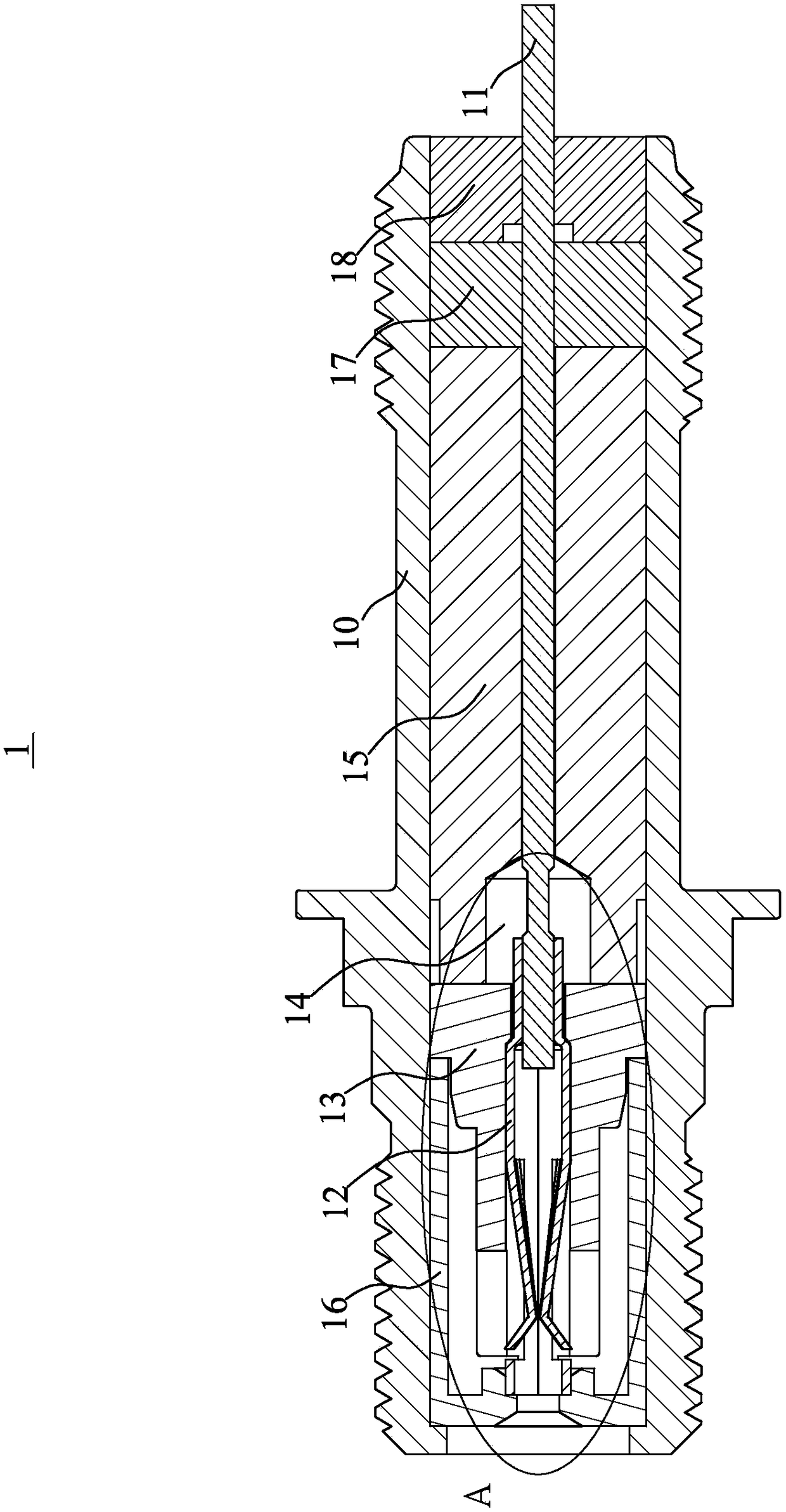
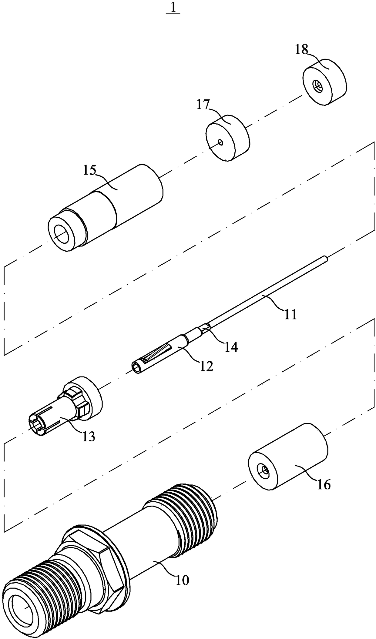
[0027] Please refer to Figure 4 to Figure 7 As shown, the electrical connector 2 of the present invention mainly includes six major structures including a housing 3 , an inner cover 4 , a pad 5 , a wire 6 , a shrapnel 7 and a stopper 8 .

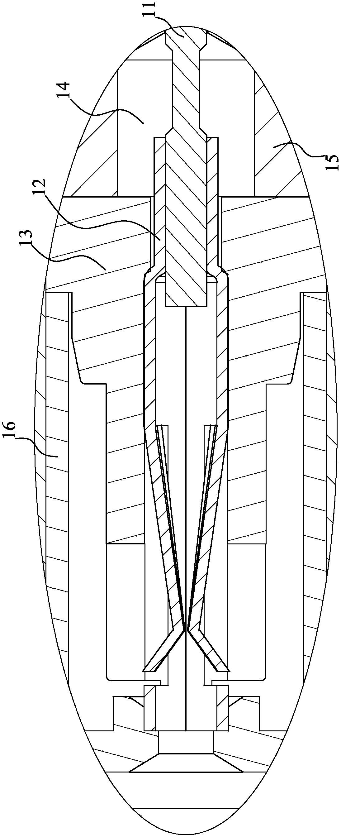
[0028] The shell 3 is mainly made of insulating plastic material, which provides a protective effect on parts such as internal wires and the parts that the human body has the opportunity to touch. The inside of the shell 3 is formed with an accommodating channel 30, and the accommodating channel Two opposite ends of the 30 respectively form a mounting hole 31 and a locking hole 32 .

[0029] The accommodating passage 30 forms a first aperture 301 , a second aperture 302 and a third aperture ...


PUM


Abstract

The invention relates to an electrical connector provided with a casing, an inner cover, a pad body, a wire and a spring piece. A receiving passage is formed in the casing. A mounting hole and an abutting hole are formed in the two opposite ends of the receiving passage respectively. The inner cover is assembled to the abutting hole of the receiving passage, and an installation channel is formed inside. The pad body is assembled to the mounting hole of the receiving passage, and a fixing channel is formed inside. The wire passes through the fixing channel of the pad body. A conductor connection section extends outwardly from the fixing channel. The elastic piece is provided with a wire clamping end and an abutting end on the opposite side. The abutting end is installed in the installationchannel of the inner cover. The clamping end is riveted to the opposite end of the conductor connection section of the wire. The clamping end is in contact with and abutted against the pad body. A space is formed between the inner wall surface of the casing and the elastic piece. Accordingly, by improving the structural design of the parts and the assembling manner between the parts, the total number of parts, the complexity of the assembly of the parts, and the assembly time of the parts can be reduced.

Description

technical field [0001] The invention relates to an electric wire connecting joint, especially a connecting joint structure capable of being combined with transmission joints of electric appliances. Background technique [0002] Generally speaking, the external surface of a common electronic device or 3C electrical product is provided with a connection terminal that can be electrically connected with other electronic devices. It is an indispensable equipment for connection, and different connection terminals are electrically connected to each other through wires with corresponding connection terminal interfaces. Since the connection terminals have different specifications and different numbers of wires, it can be used as a fool-proof design. Connecting terminals of different types can avoid the possibility of incorrect assembly. [0003] see Figure 1 to Figure 3 As shown, they are respectively shown as a longitudinal sectional schematic diagram, a three-dimensional exploded...

Claims


Application Information

Patent Timeline
Patent Type & Authority Applications(China)
IPC IPC(8): H01R13/02H01R13/502
CPCH01R13/02H01R13/502
Inventor 黄锦坤
Owner DIN IND
Why Eureka
Try Eureka