Textile fabric drying rack
A technology for textiles and drying racks, applied in the field of drying racks, which can solve the problems of inconvenient cloth, manual flattening, and long drying time, and achieve the effects of reducing work links, shortening drying time, and improving efficiency
- Summary
- Abstract
- Description
- Claims
- Application Information
AI Technical Summary
Problems solved by technology
Method used
Image

Examples
Embodiment 1
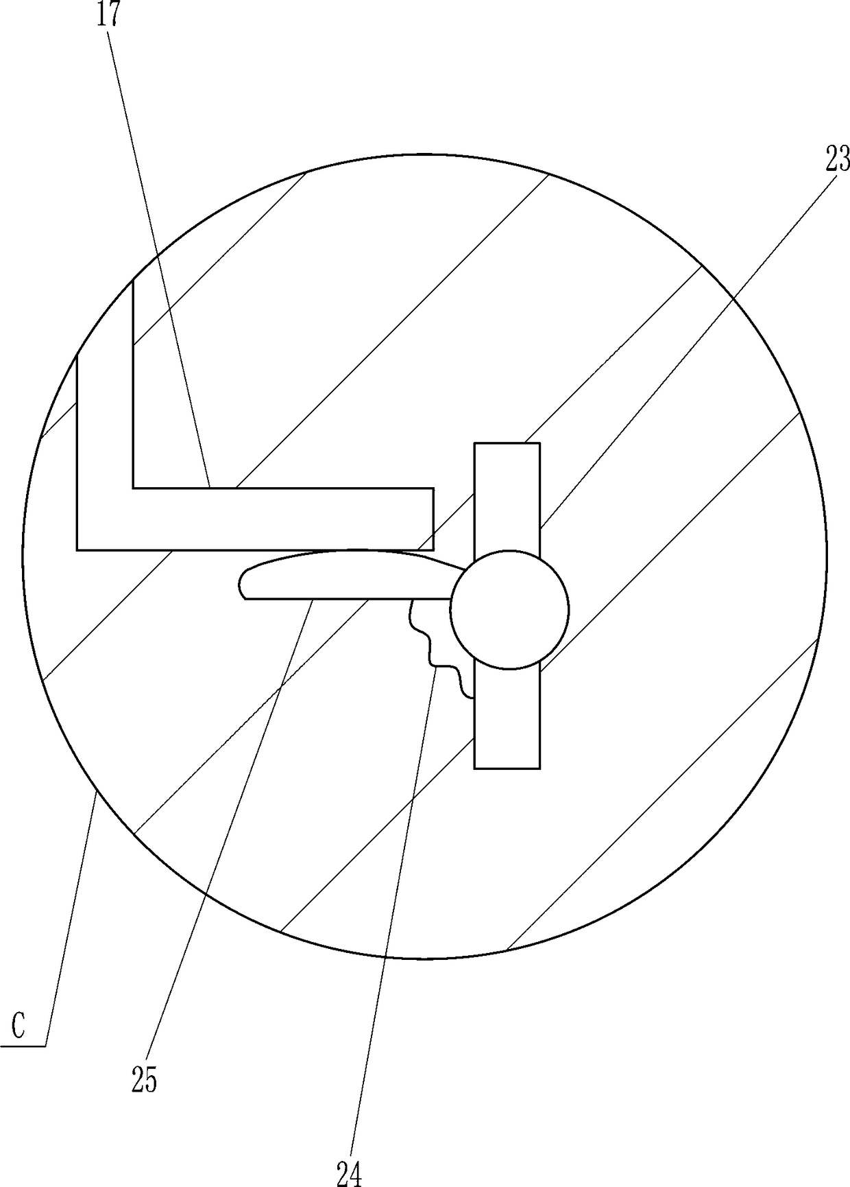
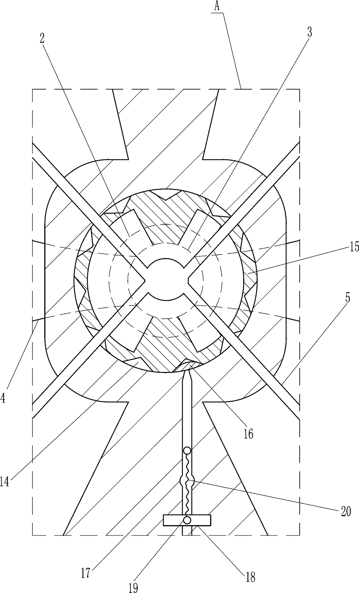
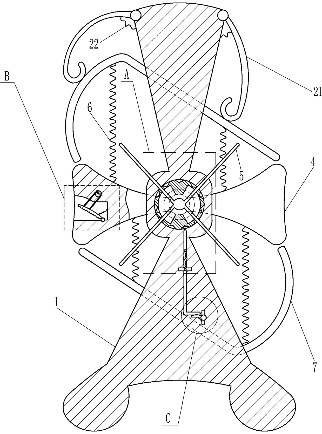
[0016] A textile cloth drying rack, such as Figure 1-3 As shown, it includes a mounting column 1, a bearing seat 2, a rotating rod 3, a rotating column 4, a first rotating frame 5, a first spring 6, a rotating plate 7, a first round head rod 9, a block 10, and a lanyard 11 , the second spring 12 and the pressure block 13, the middle part of the mounting column 1 is embedded with a bearing seat 2, and a rotating rod 3 is installed on the bearing seat 2, and the rotating rod 3 is connected with the bearing in the bearing seat 2 through an interference connection, The rear end of the rotating rod 3 is provided with a rotating column 4, and the rotating column 4 is located behind the mounting column 1. The front end of the rotating rod 3 is provided with a first rotating frame 5, and the first rotating frame 5 is located in front of the mounting column 1. Both sides are connected with the first spring 6, the rotating column 4 is connected with the first spring 6 by welding, the u...
Embodiment 2
[0018] A textile cloth drying rack, such as Figure 1-3 As shown, it includes a mounting column 1, a bearing seat 2, a rotating rod 3, a rotating column 4, a first rotating frame 5, a first spring 6, a rotating plate 7, a first round head rod 9, a block 10, and a lanyard 11 , the second spring 12 and the pressure block 13, the middle part of the mounting column 1 is embedded with a bearing seat 2, the bearing seat 2 is equipped with a rotating rod 3, the rear end of the rotating rod 3 is provided with a rotating column 4, and the rotating column 4 is located on the mounting column 1 At the rear, the front end of the rotating rod 3 is provided with a first rotating frame 5, the first rotating frame 5 is located in front of the mounting column 1, and the rotating column 4 is connected to the first spring 6 on the upper, lower, left, and right sides, and the upper end of the first spring 6 above and the lower The lower end of the first spring 6 is connected with a rotating plate ...
Embodiment 3
[0021] A textile cloth drying rack, such as Figure 1-3 As shown, it includes a mounting column 1, a bearing seat 2, a rotating rod 3, a rotating column 4, a first rotating frame 5, a first spring 6, a rotating plate 7, a first round head rod 9, a block 10, and a lanyard 11 , the second spring 12 and the pressure block 13, the middle part of the mounting column 1 is embedded with a bearing seat 2, the bearing seat 2 is equipped with a rotating rod 3, the rear end of the rotating rod 3 is provided with a rotating column 4, and the rotating column 4 is located on the mounting column 1 At the rear, the front end of the rotating rod 3 is provided with a first rotating frame 5, the first rotating frame 5 is located in front of the mounting column 1, and the rotating column 4 is connected to the first spring 6 on the upper, lower, left, and right sides, and the upper end of the first spring 6 above and the lower The lower end of the first spring 6 is connected with a rotating plate ...
PUM
 Abstract
Description
Claims
Application Information
 - R&D Engineer
- R&D Manager
- IP Professional
- Industry Leading Data Capabilities
- Powerful AI technology
- Patent DNA Extraction
Browse by: Latest US Patents, China's latest patents, Technical Efficacy Thesaurus, Application Domain, Technology Topic.
© 2024 PatSnap. All rights reserved.Legal|Privacy policy|Modern Slavery Act Transparency Statement|Sitemap