
Bottle cap locking structure

A locking structure and bottle cap technology, applied in the direction of threaded bottle caps, etc., can solve the problems of wasting manpower, etc., and achieve the effects of convenient maintenance, simple and reasonable structural design, and high efficiency

Pending Publication Date: 2019-03-12
苏州凌耀制药设备有限公司
View PDF0 Cites 2 Cited by
  • Summary
  • Abstract
  • Description
  • Claims
  • Application Information

AI Technical Summary

Problems solved by technology

[0004] Aiming at the deficiencies of the prior art, the present invention provides a bottle cap locking structure, which solves the technical problem in the prior art that the bottle cap similar to mineral water is manually tightened when tightening, which greatly wastes manpower

Method used


Image

  • Bottle cap locking structure

Examples


Embodiment Construction

[0015] The following will clearly and completely describe the technical solutions in the embodiments of the present invention with reference to the accompanying drawings in the embodiments of the present invention. Obviously, the described embodiments are only some, not all, embodiments of the present invention. Based on the embodiments of the present invention, all other embodiments obtained by persons of ordinary skill in the art without making creative efforts belong to the protection scope of the present invention.

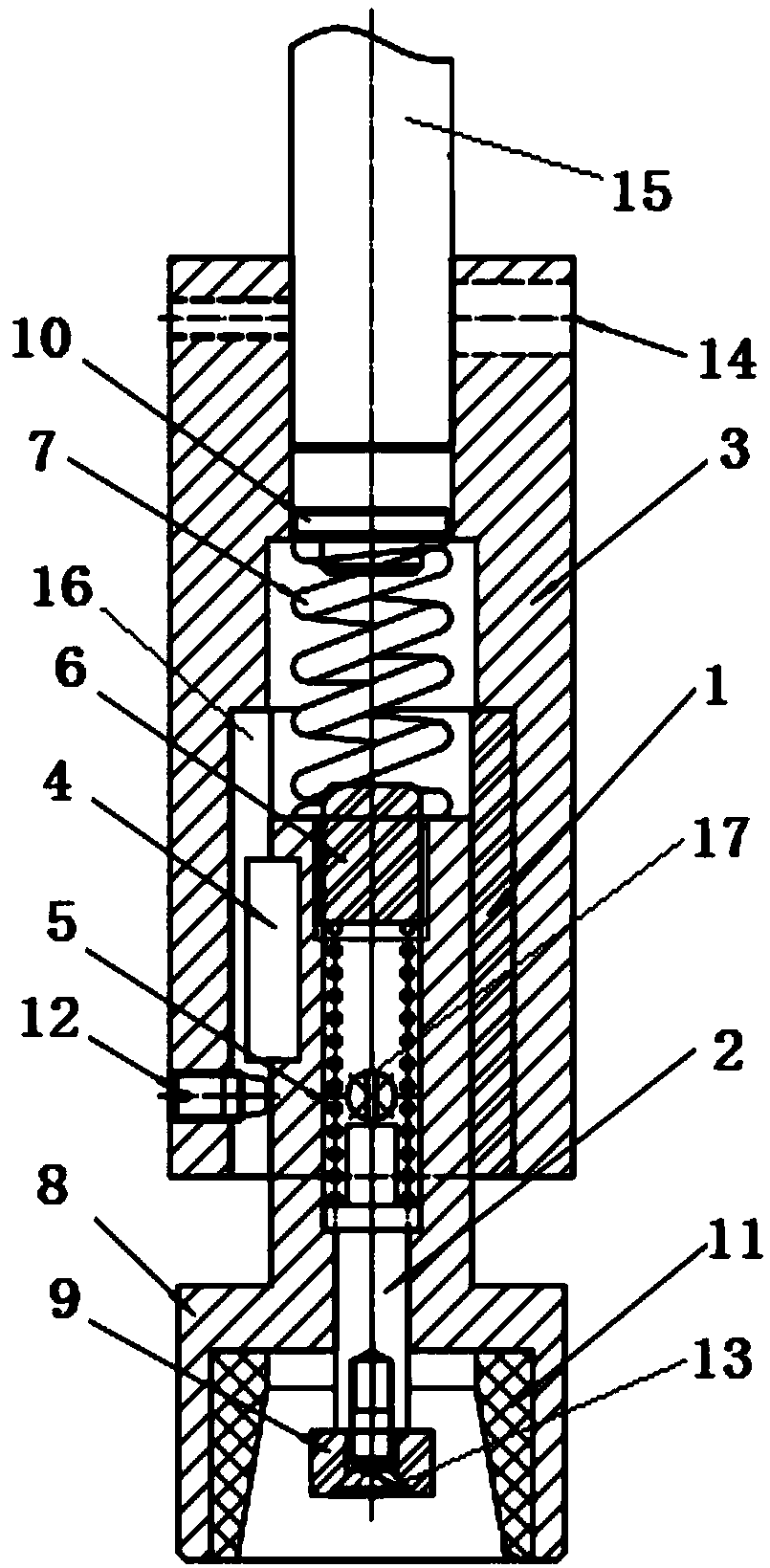
[0016] see figure 1 , the present invention provides a technical solution: a bottle cap locking structure, shaft sleeve 1, ejector rod 2, cap cover 3, key 4, inner spring 5, pressure rod 6, spring 7, cap selection head 8, push plate 9. Screw cap sleeve 11, positioning screw 12, first locking screw 13, second locking screw 14, rotating shaft 15, the inside of the screw cap cover 3 is provided with a stepped hole, and the inside of the stepped hole is provided w...


PUM


Abstract

The invention discloses a bottle cap locking structure. The bottle cap locking structure comprises a shaft sleeve, an ejector rod, a cap screwing outer sleeve, a key, an inner spring, a pressing rod,an outer spring, a cap screwing head, a push plate, a cap screwing sleeve, a locating screw, a first locking screw, a second locking screw and a rotary shaft. A step hole is formed in the cap screwingouter sleeve, and the shaft sleeve is arranged in the step hole in an interference fit manner. The shaft sleeve is in sliding connection with the cap screwing head, and the end, arranged in the shaftsleeve, of the cap screwing head is connected with a key groove through the key. The lower end of the shaft sleeve is in threaded connection with the locating screw in the radial direction, and the locating screw is located at the lower end of the key. The ejector rod is arranged in the cap screwing head, and the end, located in the cap screwing head, of the ejector rod is sleeved with the innerspring. According to the bottle cap locking structure, the torsion-adjustable cap screwing head is adopted, when a cap is screwed to reach certain torsion, automatic slipping is achieved by overcomingthe action of spring force, and it is ensured that the screwing degree is consistent; the speed is high, the efficiency is high, the structural design is simple and reasonable, and maintenance is convenient; and a bottle and a cap are not damaged, and pollution is avoided.

Description

technical field [0001] The invention relates to the technical field of bottle cap locking, in particular to a bottle cap locking structure. Background technique [0002] Bottle caps are used to seal bottles. According to different functions, there are bottle caps of different shapes and different operation methods. For example, the caps of mineral water bottles are round and used to twist, the caps of soda cans are ring-shaped and used to pull, and the caps of canned meat There is no fixed shape, it can be torn into whatever shape it is. The lid of the injection bottle is made of glass, which needs to be polished around the periphery with a grinding wheel and then popped open; the lid of the men's favorite beer bottle is pryed off. The design of the bottle cap is strange, and the designers have racked their brains to make it more innovative and attractive. [0003] Similar to the bottle caps of mineral water in the prior art, manual tightening is adopted when tightening, wh...

Claims


Application Information

Patent Timeline
Patent Type & Authority Applications(China)
IPC IPC(8): B67B3/20
CPCB67B3/20
Inventor 尚亮亮吴刚谈向锋
Owner 苏州凌耀制药设备有限公司
Learn More