Composite mold in modular design and application method of composite mold
A modular design, composite material technology, applied in the field of composite material molds, can solve the problems of difficult handling of molds for operators, heavy weight, troublesome vacuum bagging, etc., to reduce the risk of curing deformation, low density, and reduce differences. Effect
- Summary
- Abstract
- Description
- Claims
- Application Information
AI Technical Summary
Problems solved by technology
Method used
Image

Examples
preparation example Construction
[0055] The method for preparing a composite material box body using the above-mentioned composite material mold specifically includes the following steps:
[0056] Step 1: Design and prepare mold components according to the required composite material box, and set aside;
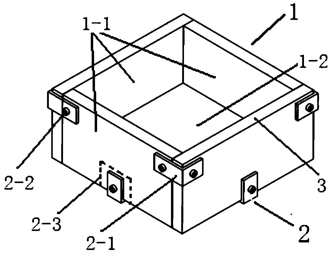
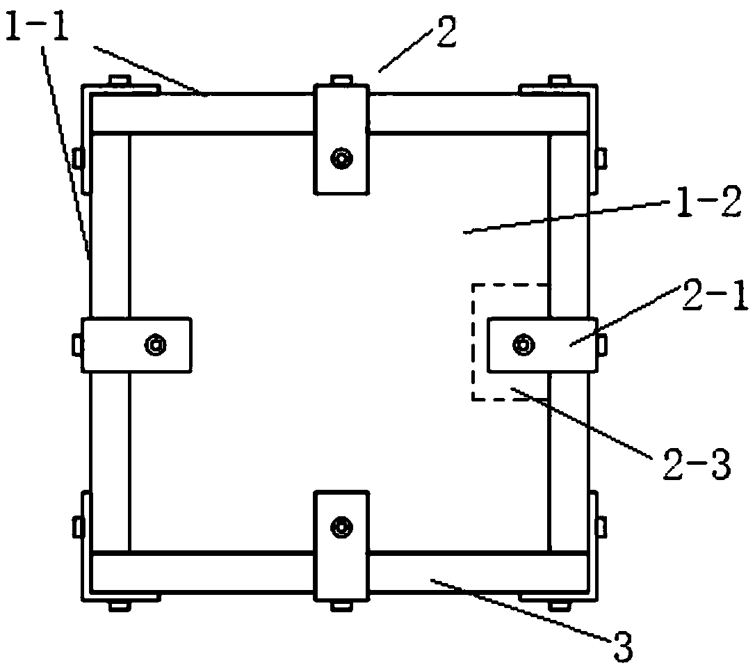
[0057] Step 2: Connect the bottom panel and several side panels together by using connecting angle pieces and bolts, and finally get the box mold;
[0058] Step 3: lay up the composite material according to the layup design;
[0059]Step 4: After the laying is completed, vacuum bag the entire box body, and the vacuum bag will completely surround the box body; when bagging, pay attention to put more air felt at the connecting corners to prevent the aluminum connecting corners from Vacuum bag puncture;
[0060] Step 5: Put it in a curing oven or an autoclave for curing;
[0061] Step 6: After curing, disassemble the vacuum bag and remove the bolts connecting the corner pieces;
[0062] Step 7: Remove the c...
Embodiment
[0072] DETAILED DESCRIPTION Taking a square box of 400mm×400mm×180mm as an example, its production and later use process will be described.
[0073] 1. Mold making
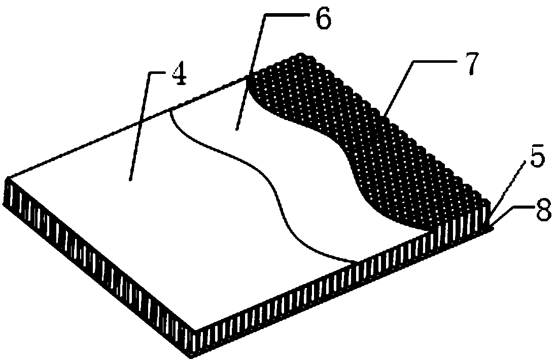
[0074] 1. Make 2 carbon fiber panels of 500mm*1000mm, the material can be plain 300 prepreg, and the layering method is [45 / 0 / 90 / 0 / 45]s. The curing method adopts hot pressing curing or vacuum bag curing. An upper panel 4 and a lower panel 8 of a sandwich structure are obtained.
[0075] 2. Take out a 500mm*1000mm aramid paper honeycomb piece with a thickness of 35mm. On the aramid paper honeycomb, draw the area that will be used to divide a bottom panel 1-1 and four side panels 1-2, namely the first side panel, the second side panel, the third side panel and the fourth side panel . And mark the position used to fill the aluminum connection block on each area to obtain the honeycomb structure 7 .
[0076] 3. According to the drawn position, dig out a 30mm×30mm square to the honeycomb structure 7. First put do...
PUM
| Property | Measurement | Unit |
|---|---|---|
| Thickness | aaaaa | aaaaa |
Abstract
Description
Claims
Application Information
 - Generate Ideas
- Intellectual Property
- Life Sciences
- Materials
- Tech Scout
- Unparalleled Data Quality
- Higher Quality Content
- 60% Fewer Hallucinations
Browse by: Latest US Patents, China's latest patents, Technical Efficacy Thesaurus, Application Domain, Technology Topic, Popular Technical Reports.
© 2025 PatSnap. All rights reserved.Legal|Privacy policy|Modern Slavery Act Transparency Statement|Sitemap|About US| Contact US: help@patsnap.com