Check patentability & draft patents in minutes with Patsnap Eureka AI!

A new energy vehicle synchronous reluctance motor control method based on AC step control

A technology for synchronous reluctance motors and new energy vehicles. It is applied in the direction of AC motor control, generator control, motor generator control, etc. It can solve problems such as the influence of calculation accuracy, poor low-speed performance, and complex system structure, and achieve improvement. Control effect, strong current followability, small torque ripple effect

Active Publication Date: 2021-08-03
HEBEI UNIV OF TECH
View PDF6 Cites 0 Cited by
  • Summary
  • Abstract
  • Description
  • Claims
  • Application Information

AI Technical Summary

Problems solved by technology

The direct torque control system is easily affected by the two-position control and the calculation accuracy of the flux linkage, resulting in large torque ripples and poor low-speed performance of the motor at low speeds
However, the traditional vector control requires complex coordinate transformation, which makes the system structure complex, the amount of calculation is large, and there are certain difficulties in practical application. Therefore, there is currently no AC step control for synchronous reluctance motor control.

Method used


Image

  • A new energy vehicle synchronous reluctance motor control method based on AC step control
  • A new energy vehicle synchronous reluctance motor control method based on AC step control
  • A new energy vehicle synchronous reluctance motor control method based on AC step control

Examples


Embodiment 1

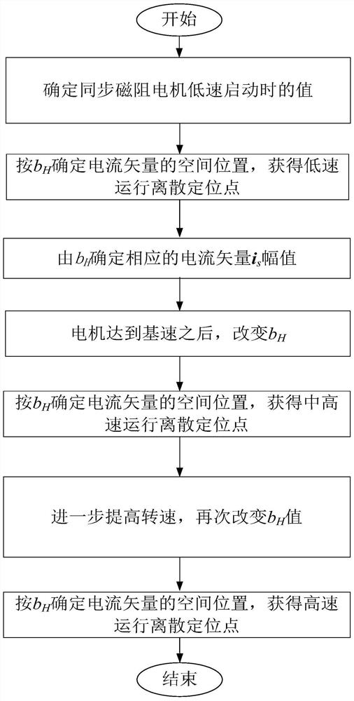
[0153] The AC stepping control method of a synchronous reluctance motor in this embodiment includes the following steps:

[0154] In this embodiment, the motor to be controlled is a salient pole rotor synchronous reluctance motor with a power of 11kw, a rated voltage of 310v, a rated current of 22.2A, and a rated speed of 1500 Rpm.

[0155] Figure 7 The illustrated embodiment shows that the composition of the device used in the operating method of the synchronous reluctance motor AC step control of the present invention includes a DSP control module 1, a power circuit 2, a synchronous reluctance motor 3, an encoder position detection module 4 and an input power supply module 5 , wherein, the input power supply module 5 supplies power for the DSP control module 1, the power circuit 2 and the encoder position detection module 3, and the DSP control module 1, the power circuit 2, the synchronous reluctance motor 3 and the encoder position detection module 4 are sequentially conn...


PUM


Abstract

The invention relates to a control method of a synchronous reluctance motor for a new energy vehicle based on AC step control. By aiming at the synchronous reluctance motor, the stator current vector synthesized by the three-phase current is discretely subdivided, and the spatial discrete positioning position is obtained according to a certain number of cycles, so that the position control of the motor is realized by controlling the spatial position of the stator magnetic field. Then speed control is realized; the proposed stepping transmission control of synchronous reluctance motor with position characteristics is just using the AC stepping control method to transform the nonlinearity of the rotor salient pole into a control difficulty that is difficult to accurately model, and transform it into a control advantage. Realize high-precision position control, and solve the shortcomings of traditional control methods such as large low-speed torque ripple and complex structure.

Description

technical field [0001] The invention relates to the technical field of AC motor transmission, in particular to a control method for synchronous reluctance motors for new energy vehicles based on AC step control. Background technique [0002] The synchronous reluctance motor has a simple structure, the stator is the same as the three-phase AC motor, and the rotor is similar to the switched reluctance motor. The synchronous motor with reluctance properties has high efficiency, high power density, easy to weaken magnetic field speed expansion, easy maintenance, and low cost. Significant advantages, high utilization value in new energy vehicle drive system. [0003] AC stepping drive control was proposed by Professor Liu Zongfu of Northeastern University in 1981. In 1996, Dr. Sun Hexu published the academic monograph "AC Stepping Drive System", which expounded it more comprehensively and systematically. Subsequently, in terms of theoretical research and engineering application...

Claims


Application Information

Patent Timeline
Patent Type & Authority Patents(China)
IPC IPC(8): H02P25/098H02P21/18
CPCH02P21/18H02P25/098
Inventor 董砚刘维佳荆锴梁晶刘学奥黄安震董冠晨刘照麟
Owner HEBEI UNIV OF TECH
Features
  • R&D
  • Intellectual Property
  • Life Sciences
  • Materials
  • Tech Scout
  • Unparalleled Data Quality
  • Higher Quality Content
  • 60% Fewer Hallucinations
Learn More