High-efficiency chemical mixing device

A mixing device and chemical technology, applied in the field of high-efficiency chemical mixing devices, can solve the problems of affecting the effect of mixing, affecting the effect of stirring, difficult to clean and maintain, and achieve the effect of enhancing the stirring effect, improving the stirring effect and facilitating daily maintenance.

Inactive Publication Date: 2019-04-30
张磊
View PDF0 Cites 3 Cited by
  • Summary
  • Abstract
  • Description
  • Claims
  • Application Information

AI Technical Summary

Problems solved by technology

[0003] However, most of the existing chemical mixing devices only drive the stirring blades to disperse the raw materials through the stirring shaft, and the materials move in the same direction with the stirring, the stirring effect is not good, and the efficiency is not hi

Method used


Image

  • High-efficiency chemical mixing device
  • High-efficiency chemical mixing device
  • High-efficiency chemical mixing device

Examples


Example Embodiment

[0023] Example one

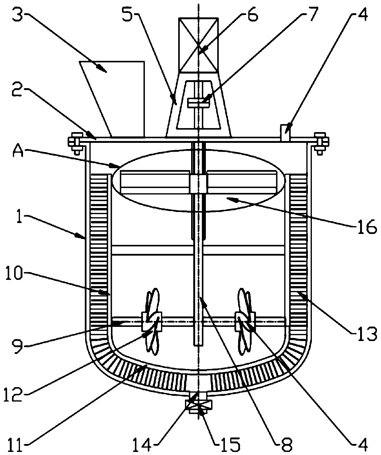
[0024] See Figure 1-3 , A high-efficiency chemical mixing device, comprising a casing 1, an upper cover 2, a hopper 3, a cleaning port 4, a motor support 5, a motor 6, a coupling 7 and a stirring shaft 8; the casing 1 is arranged above The upper cover 2 is provided with a discharge port 14 at the bottom; the upper side of the upper cover 2 is provided with a feed hopper 3 on the left side, and a cleaning port 4 is provided on the right side. A motor support 5 is installed in the center; a motor 6 is installed above the motor support 5 , A coupling 7 is set in the center; a stirring shaft 8 is fixed below the coupling 7; a defoaming device 16 is set in the middle of the stirring shaft 8, and a horizontal support rod 9 is set at the bottom; the horizontal support rod 9 is provided with or without power The outer end of the impeller 12, the horizontal support rod 9 is connected to the vertical mounting plate 10; the outside of the vertical mounting plate 10 is...

Example Embodiment

[0026] Example two

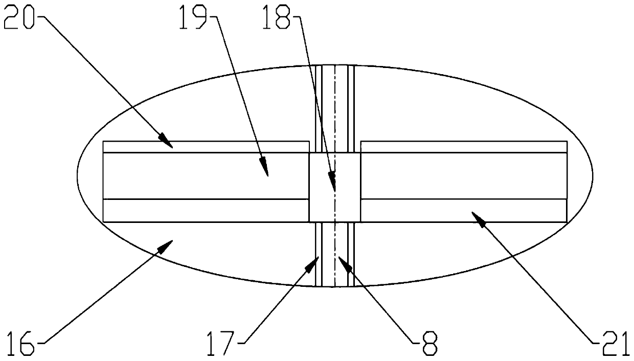
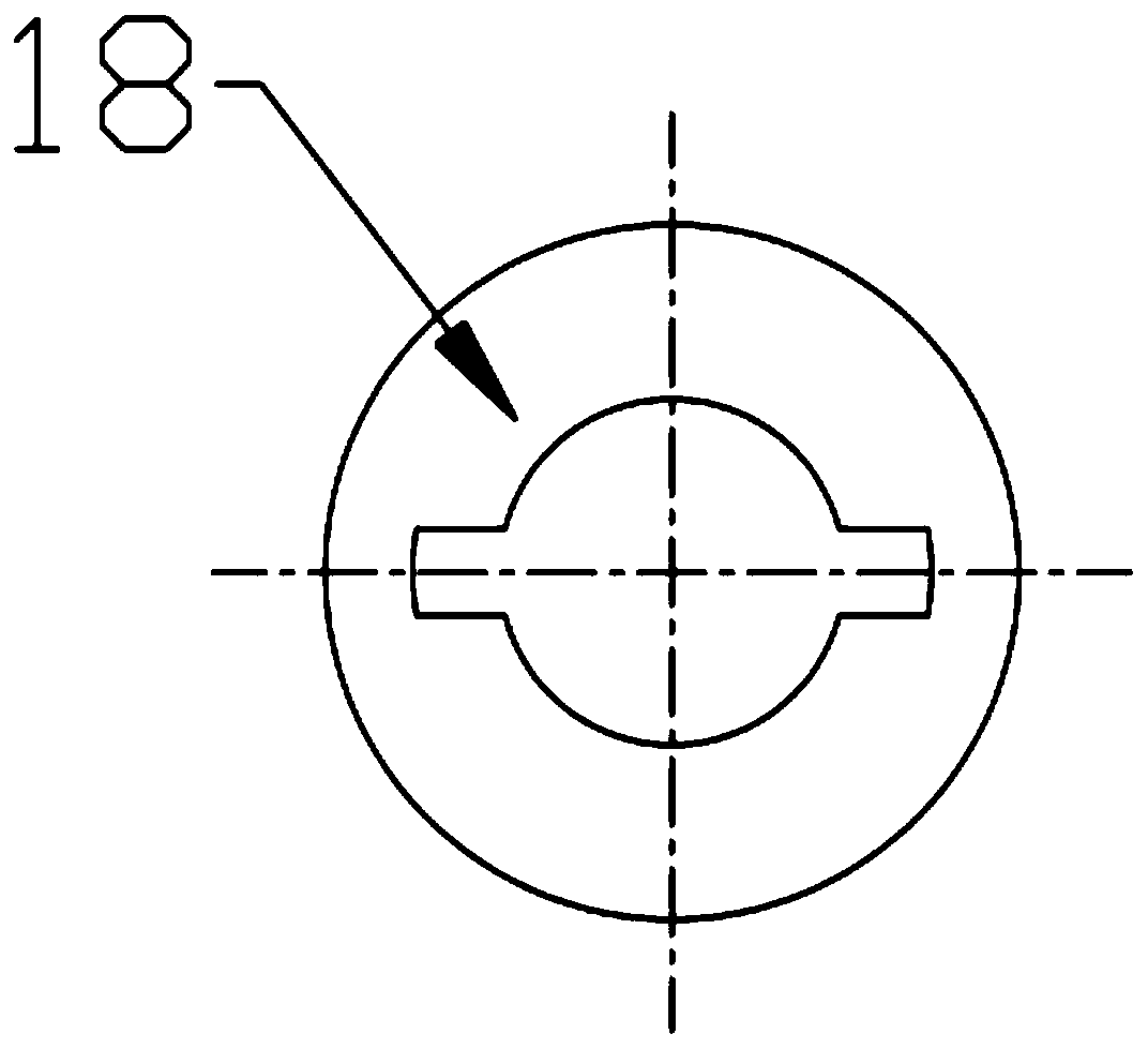
[0027] See Figure 1-3 , A high-efficiency chemical mixing device, the defoaming device 16 includes a guide sleeve 18; the left and right sides of the guide sleeve 18 are respectively provided with a defoaming rod 19; the upper surface of the defoaming rod 19 is provided with a defoaming net 20 , The lower surface is provided with a floating block 21; the guide sleeve 18 is sleeved in the middle of the stirring shaft 8 and can slide freely up and down; the middle surface of the stirring shaft 8 is provided with a guide plate 17; the guide sleeve 18 is provided with and The guide plate 17 is slidingly matched with the groove; the floating block 21 in the defoaming device 16 drives the guide sleeve 18 and the defoaming rod 19 to float up and down along the guide plate 17 on the stirring shaft 8 as the liquid level of the material changes. The bubble net 20 removes bubbles on the surface of the liquid surface and improves the mixing effect.

[0028] The working ...


PUM


Abstract

The invention discloses a high-efficiency chemical mixing device comprising a shell; an upper cover is arranged on the shell, and a discharge outlet is arranged at the bottom; a feeding hopper is arranged on the left side of the upper side of the upper cover, a cleaning port is arranged on the right side of the upper side of the upper cover, and a motor support is arranged at the center; a motor is arranged on the motor support, and a coupler is arranged at the center; a stirring shaft is fixed below the coupler; the middle part of the stirring shaft is provided with a bubble removing device,and the bottom of the stirring shaft is provided with a horizontal support rod; a powerless impeller is arranged on the horizontal support rod, and the outer end of the horizontal support rod is connected with a vertical installation plate; a cleaning brush is arranged on the outer side of the vertical installation plate. Stirring of raw materials in different directions is achieved by the powerless impeller arranged on the horizontal support rod, the stirring effect is enhanced and the stirring efficiency is improved; a floating block drives a guide sleeve to move up and down in the middle ofthe stirring shaft, bubbles are removed by a bubble removing net, and the stirring effect is improved; the cleaning brush cleans residual materials on the inner wall of the shell to prevent stickingof the raw materials, so as to be convenient for daily maintenance and improve the mixing quality.

Description

technical field [0001] The invention relates to a mixing device, in particular to a high-efficiency chemical mixing device. Background technique [0002] In chemical production, in order to process raw materials into finished products of a certain specification, a series of chemical processes such as raw material pretreatment, chemical reaction, and reaction product separation and purification are often required. The machinery used to realize these processes is often classified as chemical machinery. , in chemical production, it is almost essential to mix different raw materials, and a mixing device is required to mix different raw materials. [0003] However, most of the existing chemical mixing devices only drive the stirring blades to disperse the raw materials through the stirring shaft, and the materials move in the same direction with the stirring, the stirring effect is not good, and the efficiency is not high; There will be a lot of air bubbles floating on it, which...

Claims


Application Information

Patent Timeline
IPC IPC(8): B01F15/00B01F7/18B01F7/00B01D19/02
CPCB01D19/02B01F27/091B01F27/17B01F27/90B01F35/121
Inventor 张磊
Owner 张磊
Why Eureka
Try Eureka