Communication optical cable and manufacturing equipment

A communication optical cable and manufacturing equipment technology, applied in the direction of fiber mechanical structure, etc., can solve the problems of communication, power, broadcasting interruption, communication optical cable tearing, severe ground drop, etc., to speed up the bonding speed, reduce the impact, and improve the strength. Effect

Active Publication Date: 2020-06-02
浙江大丰管网有限公司
View PDF12 Cites 0 Cited by
  • Summary
  • Abstract
  • Description
  • Claims
  • Application Information

AI Technical Summary

Problems solved by technology

[0003] At present, there are many types of geological structures in my country, and they are relatively complex. Factors such as sea level rise, pumping of groundwater, and urban construction may cause land subsidence, especially in large sedimentary basins and coastal plain areas, where land subsidence disasters are more serious; and the new Tectonic movements and earthquakes can lead to more severe ground drops
However, the communication optical cables are laid on the low ground. When the land subsidence occurs, the communication optical cables are easily pulled and broken, resulting in the interruption of communication, power, broadcasting, etc., and affecting people's normal life.

Method used


Image

  • Communication optical cable and manufacturing equipment
  • Communication optical cable and manufacturing equipment
  • Communication optical cable and manufacturing equipment

Examples


Embodiment 1

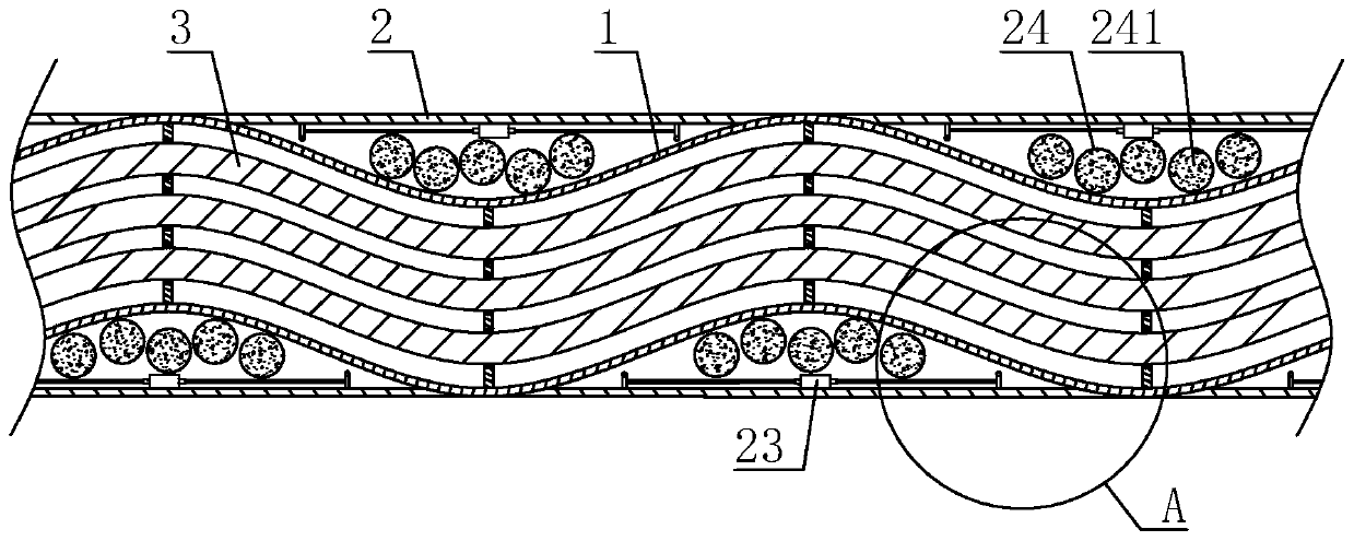
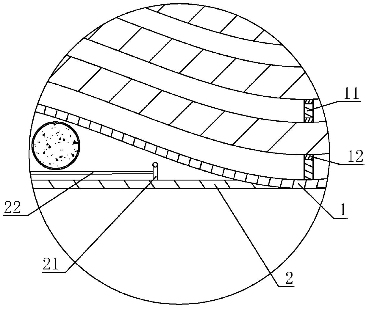
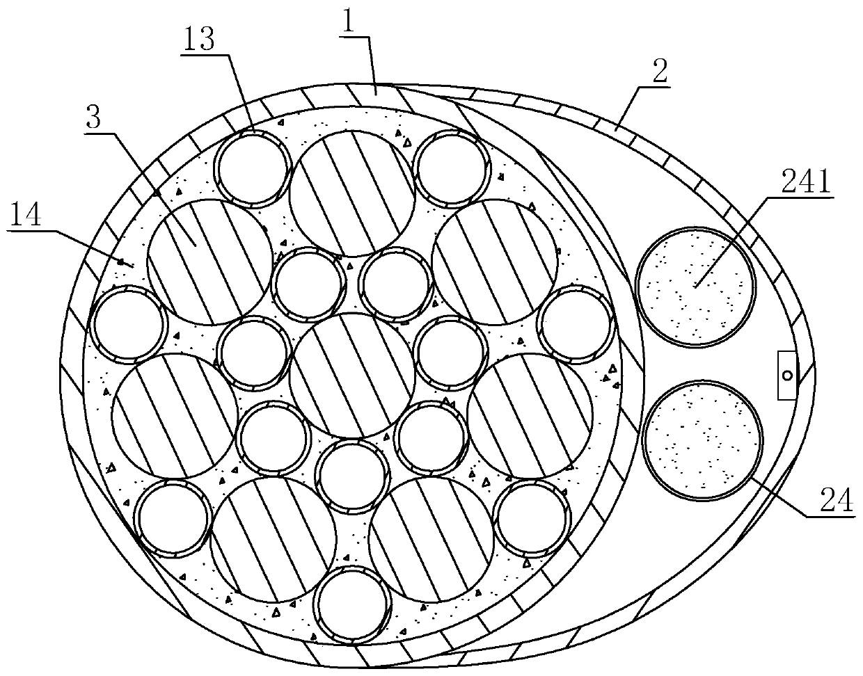
[0044] A communication optical cable, refer to figure 1 , including a protective sheath 1, the protective sheath 1 is arranged in a zigzag manner, and the optical cable body 3 is passed through the protective sheath 1. On the protective cover 1 and between the adjacent peaks, a connecting band 2 is bonded, the connecting band 2 and the protective cover 1 are made of rubber, and a closed cavity is formed between the connecting band 2 and the outer wall of the protective cover 1, And the straightened length of the protective sheath 1 connected with the connecting belt 2 is greater than the limit length of the connecting belt 2, that is, when the protective sheath 1 is straightened, the connecting belt 2 will be broken.

[0045] refer to figure 1 and figure 2 , on the side wall of the connecting belt 2 facing the airtight cavity, two pull rings 21 are fixedly arranged at intervals, and the two pull rings 21 are arranged along the extending direction of the protective cover 1, ...

Embodiment 2

[0052] A kind of manufacturing equipment, is used for manufacturing the communication optical cable in embodiment one, with reference to Figure 4 and Figure 5 , comprising a frame 4, on which two rows of hydraulic cylinders 41 are fixed along the length direction, and the two rows of hydraulic cylinders 41 are arranged in a staggered manner, and the piston rod of each hydraulic cylinder 41 is perpendicular to the length direction of the frame 4. The piston rod of the hydraulic cylinder 41 is connected with an L-shaped bending frame 42, and the short side of the bending frame 42 is fixedly connected with the piston rod of the hydraulic cylinder 41. The long side of the bending frame 42 is horizontal and used to place the first embodiment. The optical cable body 3 in the middle, and the length of the short side of the bending frame 42 is greater than the radius of the optical cable body 3 and smaller than the diameter of the optical cable body 3 .

[0053] During processing, ...


PUM


Abstract

The invention relates to a communication optical cable and manufacturing equipment and relates to the communication equipment technology field. A protection sleeve is included. The protection sleeve is arranged in a zigzag manner. A connecting belt is arranged between adjacent peaks on the protection sleeve. And a closed cavity is formed between the connecting belt and the outer wall of the protection sleeve. An optical cable body is arranged in the protection sleeve, and the length of the straightening protection sleeve connected to the connecting belt is greater than the limit length of theconnecting belt. Through the setting of the connecting belt, the elongation of the protection sleeve from a bending state to a straightening state is used as a margin for dealing with subsidence so asto greatly reduce a probability that the optical cable body in the protection sleeve is broken, reduce losses caused by a land subsidence process and reduce the impact of land subsidence on the livesof people.

Description

technical field [0001] The invention relates to the technical field of communication equipment, in particular to a laying structure of communication optical cables. Background technique [0002] The communication optical cable is composed of a cable core and an outer sheath composed of several (core) optical fibers (generally ranging from several cores to thousands of cores). Compared with traditional symmetrical copper circuits and coaxial copper circuits, optical fibers have a large transmission capacity. Much more, less attenuation, long transmission distance, small size, light weight, no electromagnetic interference, low cost, is currently the most promising communication transmission medium, it is widely used in telecommunications, electric power, broadcasting and other departments of the signal In terms of transmission, it will gradually become the main body of the future communication network. [0003] At present, there are many types of geological structures in my c...

Claims


Application Information

Patent Timeline
Patent Type & Authority Patents(China)
IPC IPC(8): G02B6/44
Inventor 李小埙李永明
Owner 浙江大丰管网有限公司
Why Eureka
Try Eureka