Mobile automatic vending machine of travelling bags

A vending machine, a technology for vending machines, applied in the directions of coin-operated equipment for distributing discrete items, coin-operated equipment for distributing discrete items, coin-operated equipment for distributing discrete items, etc., can solve the problem of increasing management Problems such as personnel burden, affecting the practicability of the device, etc., to achieve the effect of convenient movement and transfer, increased willingness, and intelligent life

Active Publication Date: 2019-05-21
武汉市鸿盛华航旅服务股份有限公司
12 Cites 0 Cited by

AI-Extracted Technical Summary

Problems solved by technology

[0003] Intelligentization is the trend of social development, and travel bags are essential items for people to travel, so travel bag vending machines have emerged as the times require. When the existing travel bag vending machines are in use, th...

Abstract

The invention, which relates to the field of vending machines, discloses a mobile automatic vending machine of travelling bags. The mobile automatic vending machine comprises a vending machine body. When the mobile automatic vending machine is in use, the odour in a perfume bag is dissipated through through holes in a grid screen plate and thus the travelling bag suspended in the vending machine body has fragrance, so that the purchasing willingness of the user is improved. Meanwhile, the perfume bag plays a role in expelling insects, so that the entrance of the insects into the vending machine body through the object taking hole and thus the probability of the damage of the travelling bag is reduced. When the vending machine is in use, the pressure on the spring is reduced after travelling bags are purchased one by one; the moving plate moves up under the effect of the elastic restoring force of the spring; the switch is pressed by the moving plate; and after the switch is turned on,the management company's internal computer receives the information and thus the management personnel can carry out replenishment timely on the corresponding vending machine, so that the usage difficulty of the device is reduced and the burden of the management personnel is reduced.

Application Domain

Coin-freed apparatus detailsApparatus for dispensing discrete articles

Technology Topic

EngineeringRestoring force

Image

  • Mobile automatic vending machine of travelling bags
  • Mobile automatic vending machine of travelling bags
  • Mobile automatic vending machine of travelling bags

Examples

  • Experimental program(1)

Example Embodiment

[0027] The technical solutions in the embodiments of the present invention will be clearly and completely described below with reference to the accompanying drawings in the embodiments of the present invention. Obviously, the described embodiments are only a part of the embodiments of the present invention, but not all of the embodiments. Based on the embodiments of the present invention, all other embodiments obtained by those of ordinary skill in the art without creative efforts shall fall within the protection scope of the present invention.
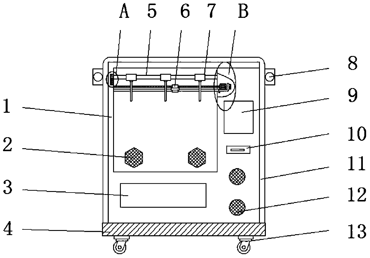
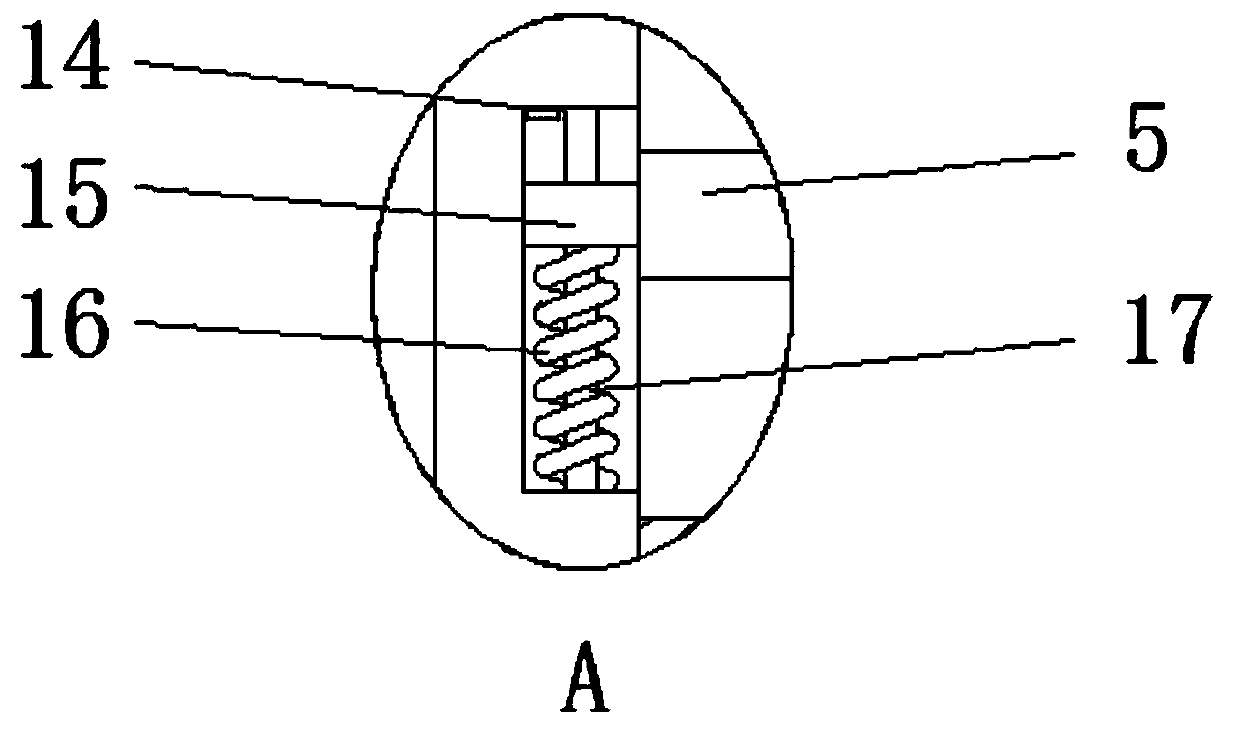
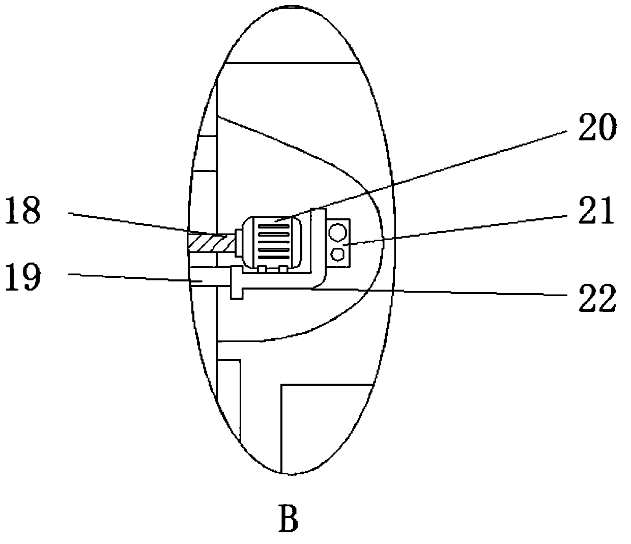
[0028] see Figures 1 to 6 , In the embodiment of the present invention, the travel bag mobile vending machine includes a vending machine body 1, the lower surface of the vending machine body 1 is fixedly connected with a base 4, and the four corners of the lower surface of the base 4 are installed with locking The universal wheel 13 facilitates the movement of the entire device by locking the universal wheel 13 and reduces the difficulty of using the device; and the outer surface of the vending machine body 1 near the top is fixedly connected with two symmetrically arranged lifting rings 8, and through the lifting rings 8 To facilitate the hoisting of the whole device, the front end face of the vending machine body 1 is rotatably connected with a movable door 11, the movable door 11 is provided with a pick-up port 3, and the front end face of the vending machine body 1 is also installed with a touch display screen 9, an entrance Note 10 and audio 12; the vending machine body 1 is equipped with a rope hanging mechanism for hanging a travel bag, and a shearing mechanism 6 is installed in the vending machine body 1, and a driving mechanism is installed in the vending machine body 1 The X-axis drive mechanism and the Y-axis drive mechanism that the shearing mechanism 6 moves in the X-axis direction and the Y-axis direction, through the X-axis driving mechanism and the Y-axis driving mechanism, the shearing mechanism 6 is moved and cut off the rope hanging mechanism. The vending machine body 1 is equipped with an aromatherapy mechanism 2, and the vending machine body 1 is equipped with a replenishment automatic trigger mechanism through the aromatherapy mechanism 2 to make the automatic replenishment trigger mechanism installed in the vending machine body 1. Trigger agency timing to remind managers to replenish in time.
[0029] The rope hanging mechanism is composed of a support frame 5 and a positioning block 7. The vending machine body 1 is provided with a support frame 5. The support frame 5 is fixedly connected with a plurality of positioning blocks 7 evenly distributed in a matrix shape. The lower surface of the 7 is tied with a cord for attaching the travel bag.
[0030] The X-axis drive mechanism is composed of a transverse threaded rod 18, a limit rod 1 19 and a motor 1 20. The vending machine body 1 is provided with a transversely arranged transverse threaded rod 18, and one end of the transverse threaded rod 18 is connected to the vending machine body. The inner wall of 1 is slidably connected, the other end of the transverse threaded rod 18 is connected with the output end of the motor one 20 through the coupling, and the vending machine body 1 is slidably connected with a horizontally arranged limit rod one 19, which works through the motor one 20. The connecting plate 605 moves along the transversely threaded rod 18, thereby causing the shearing mechanism 6 to perform transverse movement.
[0031]The Y-axis drive structure is composed of a connecting block 21, a mounting plate 22, a longitudinal threaded rod 24, a second limit rod 25 and a second motor 26. The vending machine body 1 is fixedly connected with the mounting plate 22, the second motor 26, and the second motor. The output end of the two 26 is connected to one end of the longitudinal threaded rod 24 through a coupling, the other end of the longitudinal threaded rod 24 is rotatably connected with the vending machine body 1, and the longitudinal threaded rod 24 penetrates the connecting block 21 and is threadedly connected with the connecting block 21, and The vending machine body 1 is fixedly connected with a second limit rod 25 arranged longitudinally, and the connecting block 21 penetrates through the second limit rod 25 and is slidably connected with the second limit rod 25; the connecting block 21 is fixedly connected with the mounting plate 22, and the motor Both the first 20 and the limit rod 1 19 are fixedly connected with the mounting plate 22, and the second motor 26 works to make the connecting block 21 move along the longitudinal threaded rod 24, thereby driving the mounting plate 22, the X-axis drive mechanism and the shearing mechanism 6 to perform Longitudinal movement, through the lateral movement and longitudinal movement of the shearing mechanism 6, the shearing mechanism 6 can move in a plane, thereby cutting the ropes at different positions.
[0032] The shearing mechanism 6 consists of a movable shearing block 601, a fixed shearing block 602, a sliding block 603, an electric push rod 604 and a connecting plate 605. The transverse threaded rod 18 penetrates the connecting plate 605 and is threadedly connected with the connecting plate 605. And the limit rod one 19 penetrates through the connecting plate 605 and is slidably connected with the connecting plate 605; the connecting plate 605 is fixedly connected with a fixed shear block 602, and one side of the fixed shear block 602 is provided with a matching dynamic shear block 601, One end of the moving shear block 601 is fixedly connected with a sliding block 603, the sliding block 603 is slidably connected in the chute opened by the connecting plate 605, and is fixedly connected with the output end of the electric push rod 604 installed in the chute. After payment is made by the banknote port 10 or the two-dimensional code displayed on the touch screen 9, the electric push rod 604 in the cutting mechanism 6 works by manipulating the touch screen 9, so that the movable cutting block 601 faces the fixed cutting block 602. Movement, the rope is cut through the movable shearing block 601 and the fixed shearing block 602, so that the travel bag can be taken out from the take-out port 3, so as to realize the automatic sale of the travel bag, reduce personnel costs, and because of the universal locking The wheel 13 enables the device to be conveniently moved and transported, so that the user can conveniently purchase the travel bag, making the user's life more intelligent and efficient.
[0033] The aromatherapy mechanism 2 is composed of a magnet 201, a fragrance package 202, a box body 203 and a grid mesh door 204. The vending machine body 1 is provided with a box body 203, and the box body 203 is filled with the fragrance package 202, and the box One side of the body 203 is fixedly connected with a magnet 201, through which the box 203 is adsorbed in the vending machine body 1, and the other side of the box 203 is rotatably connected with a grid mesh door 204, the fragrance package 202 is non-woven The cloth is composed of natural fragrance (lavender), and the smell in the fragrance bag 202 is dissipated through the through holes in the grid mesh door 204, so that the travel bag hanging in the vending machine body 1 becomes fragrant, thereby improving the user's willingness to buy, At the same time, the spice bag 202 also plays the role of repelling insects, reducing the entry of insects and ants into the vending machine body 1 through the extraction port 3, thereby reducing the probability of damage to the travel bag.
[0034] The automatic replenishment trigger mechanism is composed of a switch 14, a moving block 15, a spring 16 and a straight rod 17, the support frame 5 is slidably connected to the inner wall of the vending machine body 1, and the support frame 5 is fixedly connected with a moving block 15, which moves The block 15 is slidably connected in the installation groove opened by the vending machine body 1, wherein the switch 14 is installed on the upper inner wall of the installation groove, and the vertical straight rod 17 is fixedly connected in the installation groove. The moving block 15 is slidably connected, and the straight rod 17 is strung with a spring 16. The two ends of the spring 16 are distributed and connected to the moving block 15 and the inner bottom wall of the installation groove. When the travel bag is gradually purchased, the spring 16 receives The pressure decreases, and under the action of the elastic restoring force of the spring 16, the movement plate 15 moves upward, and the switch 14 is squeezed through the movement plate 15. The switch 14 is used to control the signal generator installed in the vending machine body 1. The device communicates with the internal computer of the management company through the 4g module. When the switch 14 is turned on, the internal computer of the management company receives the information, and since each vending machine body 1 is provided with a specific number, the management personnel can timely correspond to the corresponding The vending machine body 1 can be replenished, which reduces the difficulty of using the device and reduces the burden on the management personnel.
[0035] In particular, when the present invention is in use, the vending machine body 1 has a built-in specific program (this is the prior art), so that the cutting mechanism 6 works according to the law from back to front, and thus from left to right, that is, cutting first and last A row of ropes, when cutting the last row of ropes, work according to the law of left to right, when the last row is cut, cut the ropes of the previous row according to the law of left to right, and then analogy.
[0036] The circuits and controls involved in the present invention are all in the prior art, and are not described in detail here. The above-mentioned electrical components are connected to the commercial power through a power cord (not shown in the figure), and are powered by the commercial power.
[0037] In the description of the present invention, it should be noted that the terms "center", "upper", "lower", "left", "right", "vertical", "horizontal", "front", "rear", etc. The indicated orientation or positional relationship is based on the orientation or positional relationship shown in the accompanying drawings, which is only for the convenience of describing the present invention and simplifying the description, rather than indicating or implying that the indicated device or element must have a specific orientation or a specific orientation. Therefore, it should not be construed as a limitation on the present invention. In the present invention, it should be noted that the terms "installation" and "connection" should be understood in a broad sense, for example, it may be a fixed connection or a detachable connection, or The integrally formed connection may also be a mechanical connection or an indirect connection through an intermediate medium, and the specific meanings of the terms in the present invention can be understood through specific circumstances.
[0038] It will be apparent to those skilled in the art that the present invention is not limited to the details of the above-described exemplary embodiments, but that the present invention may be embodied in other specific forms without departing from the spirit or essential characteristics of the invention. Therefore, the embodiments are to be regarded in all respects as illustrative and not restrictive, and the scope of the invention is defined by the appended claims rather than the foregoing description, which are therefore intended to fall within the scope of the appended claims. All changes within the meaning and scope of the equivalents of , are included in the present invention. Any reference signs in the claims shall not be construed as limiting the involved claim.
[0039] In addition, it should be understood that although this specification is described in terms of embodiments, not each embodiment only includes an independent technical solution, and this description in the specification is only for the sake of clarity, and those skilled in the art should take the specification as a whole , the technical solutions in each embodiment can also be appropriately combined to form other implementations that can be understood by those skilled in the art.

PUM

no PUM

Description & Claims & Application Information

We can also present the details of the Description, Claims and Application information to help users get a comprehensive understanding of the technical details of the patent, such as background art, summary of invention, brief description of drawings, description of embodiments, and other original content. On the other hand, users can also determine the specific scope of protection of the technology through the list of claims; as well as understand the changes in the life cycle of the technology with the presentation of the patent timeline. Login to view more.

Similar technology patents

Wiring board fixing jig and automatic electric box assembling device

ActiveCN103419156AIncrease productivityReduce personnel costs
Owner:GREE ELECTRIC APPLIANCES INC OF ZHUHAI

Stirring tank overflow recovery system and control method thereof

PendingCN111957262Aavoid wastingReduce personnel costs
Owner:中冶北方(大连)工程技术有限公司

Purchase-sale-stock management system based on online shopping mall sales

PendingCN111080203AReduce personnel costsReduce the burden on
Owner:苏州网瑞信息技术有限公司

Intelligent automatic sorting and weighing device

InactiveCN106000901AImprove work efficiencyReduce personnel costs
Owner:洪根军

User environment delivery method and device for SaaS (Software as Service) and medium

PendingCN114546597AImprove delivery efficiencyReduce personnel costs
Owner:SHANDONG INSPUR GENESOFT INFORMATION TECH CO LTD

Classification and recommendation of technical efficacy words

  • Reduce personnel costs
  • low price

Visualized big data workflow configuration method and system based on WEB

InactiveCN108037919AImprove development efficiencyReduce personnel costs
Owner:北京博宇通达科技有限公司

Metal separator

InactiveCN105479620AReduce personnel costsReduce labor intensity
Owner:合肥光裕机械有限责任公司

Wiring board fixing jig and automatic electric box assembling device

ActiveCN103419156AIncrease productivityReduce personnel costs
Owner:GREE ELECTRIC APPLIANCES INC OF ZHUHAI

Intelligent automatic sorting and weighing device

InactiveCN106000901AImprove work efficiencyReduce personnel costs
Owner:洪根军

Purchase-sale-stock management system based on online shopping mall sales

PendingCN111080203AReduce personnel costsReduce the burden on
Owner:苏州网瑞信息技术有限公司
Why Eureka
Try Eureka