Distance measuring sensor
A distance measurement and sensor technology, applied in the field of distance measurement sensors, can solve problems such as high manufacturing costs and expanding the physical size of the optical system
- Summary
- Abstract
- Description
- Claims
- Application Information
AI Technical Summary
Problems solved by technology
Method used
Image

Examples
no. 1 example
[0034] The first embodiment is described below. The distance measurement sensor according to the present embodiment is mounted to a vehicle, and it is configured to measure the distance between the vehicle and an object by light transmission and light reception. This specification describes a frequency modulated continuous wave (hereinafter "FMCW") distance measurement sensor that calculates the distance to an object by heterodyne detection that combines transmitted and received beams and checks for frequency differences.
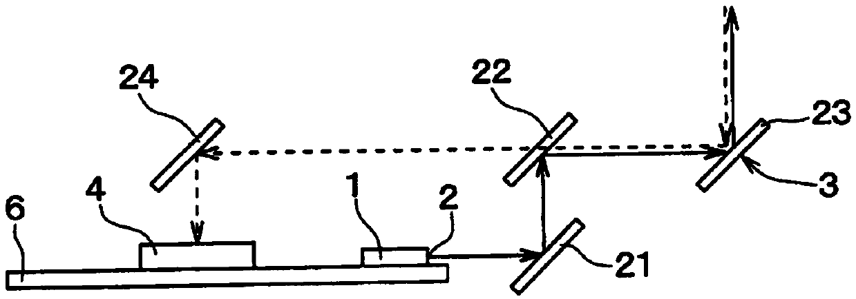
[0035] Such as figure 1 with figure 2 As shown, the distance measurement sensor includes: a light source 1; an emitter 2 for emitting light generated by the light source 1 to the outside of the light source 1; and a scanner 3 configured to perform scanning using a light beam emitted from the emitter 2 . The distance measurement sensor further includes: an optical receiver 4 configured to receive a light beam from the outside; and a processor 5 configure...
no. 2 example
[0091] The second embodiment is described below. Compared with the first embodiment, the present embodiment involves modification of the configuration of the chip 15 . Since other parts in this embodiment are similar to those in the first embodiment, only the parts different from the first embodiment will be described below.
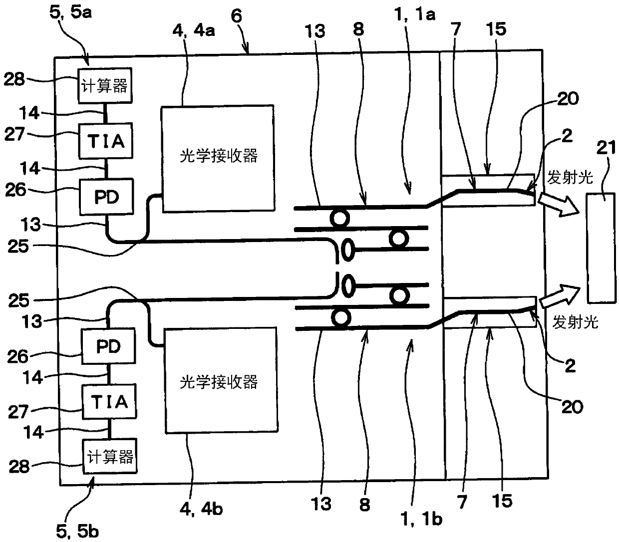
[0092] Figure 7 It is shown that the distance measuring sensor according to the present embodiment comprises a single chip 15 with two SOAs 7 . The two transmitters 2 are each configured by two optical waveguides 20 in a single chip 15 . Notice Figure 7 Illustration of the optical receiver 4, the processor 5, and the like is omitted.
[0093] Since the two SOAs 7 are located in a single chip 15, the number of components can be reduced, thereby reducing the size of the distance measuring sensor. Therefore, it is easier to manufacture distance measuring sensors. Furthermore, the cost of manufacturing the distance measuring sensor can be further red...
no. 3 example
[0095] The third embodiment is described below. Compared with the first embodiment, this embodiment involves a modification of the method for identifying a light source. Since other parts in this embodiment are similar to those in the first embodiment, only the parts different from the first embodiment will be described below.
[0096] In this embodiment, the frequency of the light beam emitted from one of the two emitters 2 is different from the frequency of the light beam emitted from the other of the two emitters 2 . For example, the difference on the order of THz is between fA0, fA1 and fB0, fB1.
[0097] By providing a frequency difference, the processor 5 can detect the beat frequency, as described below. When the light beam emitted from the light source 1a is incident on the optical receiver 4a, a beat frequency equal to or less than GHz order (for example, about 1 GHz) can be detected in heterodyne detection, as shown by Figure 8 Indicated by arrows A and B. On th...
PUM
 Abstract
Description
Claims
Application Information
 - R&D
- Intellectual Property
- Life Sciences
- Materials
- Tech Scout
- Unparalleled Data Quality
- Higher Quality Content
- 60% Fewer Hallucinations
Browse by: Latest US Patents, China's latest patents, Technical Efficacy Thesaurus, Application Domain, Technology Topic, Popular Technical Reports.
© 2025 PatSnap. All rights reserved.Legal|Privacy policy|Modern Slavery Act Transparency Statement|Sitemap|About US| Contact US: help@patsnap.com