Unlock instant, AI-driven research and patent intelligence for your innovation.

Correction method and correction device

A calibration method and a calibration device technology, which are applied to measuring devices, optical devices, instruments, etc., and can solve problems such as large devices and large physical spaces

Inactive Publication Date: 2019-05-24
KYOCERA CORP
View PDF9 Cites 1 Cited by
  • Summary
  • Abstract
  • Description
  • Claims
  • Application Information

AI Technical Summary

Problems solved by technology

Therefore, the apparatus to perform the correction is larger and requires a larger physical space

Method used


Image

  • Correction method and correction device
  • Correction method and correction device
  • Correction method and correction device

Examples


Embodiment Construction

[0061] Hereinafter, embodiments of the present invention will be described with reference to the drawings. In addition, the figures used in the following description are schematic figures. Dimensional ratios and the like in the drawings do not necessarily agree with actual conditions.

[0062] In this disclosure, determining the relationship between an image captured by a camera and a stereo camera and an ideal image is referred to as "correction". The result of the correction is obtained, for example, as a correction parameter. The correction parameters are obtained, for example, as the camera's offset to the horizontal and vertical directions, the offset angle of the optical axis, and / or the rotation angle of the camera around the optical axis. Also, in the present disclosure, correcting the image data output from the camera based on the result of the correction is referred to as "correction".

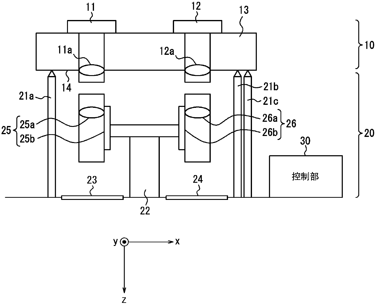
[0063] use figure 1 as well as figure 2 The configuration of the calibration...


PUM


Abstract

The present invention provides a correction method and a correction device that can correct a shift in the optical axis direction of a stereo camera without requiring a large space. The offset of theoptical axis directions (11c, 12c) of the first camera (11) and the second camera (12) of the stereo camera (10) fixed by the camera support (13) is corrected. The reference surface of the camera support (13) is positioned with respect to a predetermined reference plane for calibration. The first optical adjustment device (25) and the second optical adjustment device (26) are operated, and the first target (23) and the second target (24) located at a plurality of virtual positions different from each other are captured to acquire a plurality of The first image and the second image. The first parameter ([theta]1, [phi]1) of offset in the direction of a first optical axis 11c and a second parameter ([theta]2, [phi]2) of the offset in the direction of a second optical axis 12c are calculated.

Description

technical field [0001] The present invention relates to a correction method and a correction device for correcting deviation in the optical axis direction of a stereo camera device. Background technique [0002] A stereo camera is mounted on a vehicle or the like, and is used to recognize surrounding obstacles, determine a distance, and the like. The stereo camera has two cameras arranged in parallel and equipotentially, and determines the distance by detecting displacement due to parallax on a pixel-by-pixel or sub-pixel basis from images captured by the cameras. Therefore, in the stereo camera, the measurement accuracy is greatly affected by distortion of the image, displacement of the position of the camera, displacement of the optical axis direction of the camera, and the like. [0003] In particular, even if the optical axis is adjusted for each camera in a single state, when a camera support body supporting two cameras is assembled to form a stereo camera, due to erro...

Claims


Application Information

Patent Timeline
Patent Type & Authority Applications(China)
IPC IPC(8): H04N13/218G01B11/00H04N23/90
Inventor 大原直人
Owner KYOCERA CORP