A hydraulic lift locking method
A technology of hydraulic lifting and hydraulic lifter, applied in the direction of lifting device, etc., can solve the problems of inability to effectively ensure the balance of the load on the suspended object, the inability to achieve multi-point locking load balance, poor operation reliability and safety, etc., and to improve the locking reliability. The effect of reducing the hoisting risk and improving the safety of the operation
- Summary
- Abstract
- Description
- Claims
- Application Information
AI Technical Summary
Problems solved by technology
Method used
Image

Examples
Embodiment 1
[0038] A hydraulic lifting locking method, comprising the following steps:
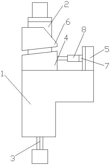
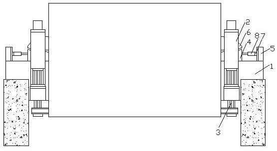
[0039] a. Fix one end of the lifting rope 3 in the hydraulic lifting locking device on the hanging object, and pass through the hydraulic lifting device 2 to lock;
[0040] b. Loosen the lower lock of the hydraulic lifter 2, the oil cylinder of the hydraulic lifter 2 shrinks and runs, the hanging object falls by one cylinder stroke, the lower lock is clamped, the upper lock is released, the oil cylinder stretches out and runs one cylinder stroke, and the rope is lifted 3. Move one stroke length of the oil cylinder into the hydraulic lifter 2, and drop the hanging object by one stroke height;
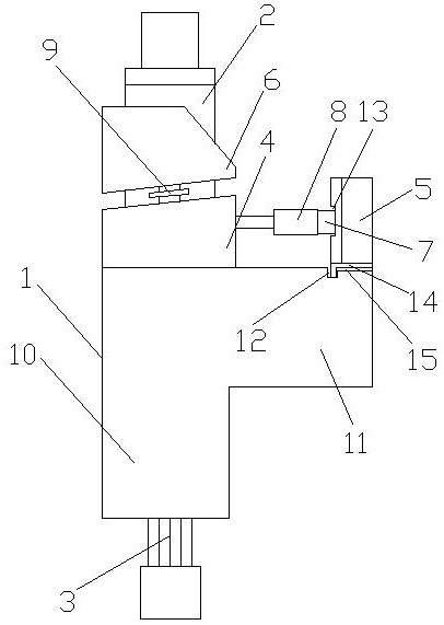
[0041] c. When the hanging object reaches the locking position, the wedge-shaped locking seat 4 is pushed out by the jack 8 and contacts the locking support 6 on the surface of the hanging object, and the height of the hanging object is adjusted by relying on the inclined plane at the joint between the wedge-sha...
Embodiment 2
[0045] A hydraulic lifting locking method, comprising the following steps:
[0046] a. Fix one end of the lifting rope 3 in the hydraulic lifting locking device on the hanging object, and pass through the hydraulic lifting device 2 to lock;
[0047] b. Loosen the lower lock of the hydraulic lifter 2, the oil cylinder of the hydraulic lifter 2 shrinks and runs, the hanging object falls by one cylinder stroke, the lower lock is clamped, the upper lock is released, the oil cylinder stretches out and runs one cylinder stroke, and the rope is lifted 3. Move one stroke length of the oil cylinder into the hydraulic lifter 2, and drop the hanging object by one stroke height;
[0048] c. When the hanging object reaches the locking position, the wedge-shaped locking seat 4 is pushed out by the jack 8 and contacts the locking support 6 on the surface of the hanging object, and the height of the hanging object is adjusted by relying on the inclined plane at the joint between the wedge-sha...
Embodiment 3
[0054] A hydraulic lifting locking method, comprising the following steps:
[0055] a. Fix one end of the lifting rope 3 in the hydraulic lifting locking device on the hanging object, and pass through the hydraulic lifting device 2 to lock;
[0056] b. Loosen the lower lock of the hydraulic lifter 2, the oil cylinder of the hydraulic lifter 2 shrinks and runs, the hanging object falls by one cylinder stroke, the lower lock is clamped, the upper lock is released, the oil cylinder stretches out and runs one cylinder stroke, and the rope is lifted 3. Move one stroke length of the oil cylinder into the hydraulic lifter 2, and drop the hanging object by one stroke height;
[0057] c. When the hanging object reaches the locking position, the wedge-shaped locking seat 4 is pushed out by the jack 8 and contacts the locking support 6 on the surface of the hanging object, and the height of the hanging object is adjusted by relying on the inclined plane at the joint between the wedge-sha...
PUM
 Abstract
Description
Claims
Application Information
 - R&D
- Intellectual Property
- Life Sciences
- Materials
- Tech Scout
- Unparalleled Data Quality
- Higher Quality Content
- 60% Fewer Hallucinations
Browse by: Latest US Patents, China's latest patents, Technical Efficacy Thesaurus, Application Domain, Technology Topic, Popular Technical Reports.
© 2025 PatSnap. All rights reserved.Legal|Privacy policy|Modern Slavery Act Transparency Statement|Sitemap|About US| Contact US: help@patsnap.com