Material transportation overturning device

A technology of turning devices and materials, applied in the directions of transportation and packaging, conveyor objects, etc., can solve the problems of low production efficiency and high labor intensity, achieve the effect of simple structure, reduce labor intensity, and avoid manual turning of materials

Pending Publication Date: 2019-06-14
XINBANG METAL PROD KUNSHAN
0 Cites 0 Cited by

AI-Extracted Technical Summary

Problems solved by technology

The existing processing equipment usually does not have a material turning device, and usually relies on workers to manu...

Abstract

The invention discloses a material transportation overturning device, which comprises a shearing die arranged on a frame and used for shearing raw materials, a claw hand and a material direction changing unit, wherein the raw materials are sheared into to-be-processed material sections with the central axis being in a horizontal state by the shearing die; the claw hand is used for grasping and horizontally moving the to-be-processed material sections; the material direction changing unit is disposed on the frame and located on one side of the shearing die for changing the central axis of the to-be-processed material sections from the horizontal state to a vertical state; the material direction changing unit comprises a direction changing block, a groove is formed on the direction changingblock, and an arc-shaped guide surface, which abuts against the to-be-processed material sections when the to-be-processed material sections horizontally move to the direction changing block under thedriving of the claw hand and causes the central axis of the to-be-processed material sections to change from the horizontal state to the vertical state, is formed in the groove. The material transportation overturning device has the advantages of simple structure and convenient use

Application Domain

Conveyor parts

Technology Topic

EngineeringMaterial transport +1

Image

  • Material transportation overturning device
  • Material transportation overturning device
  • Material transportation overturning device

Examples

  • Experimental program(1)

Example Embodiment

[0022] The present invention will be further described in detail below with reference to the accompanying drawings, so that those skilled in the art can implement it with reference to the text of the description.
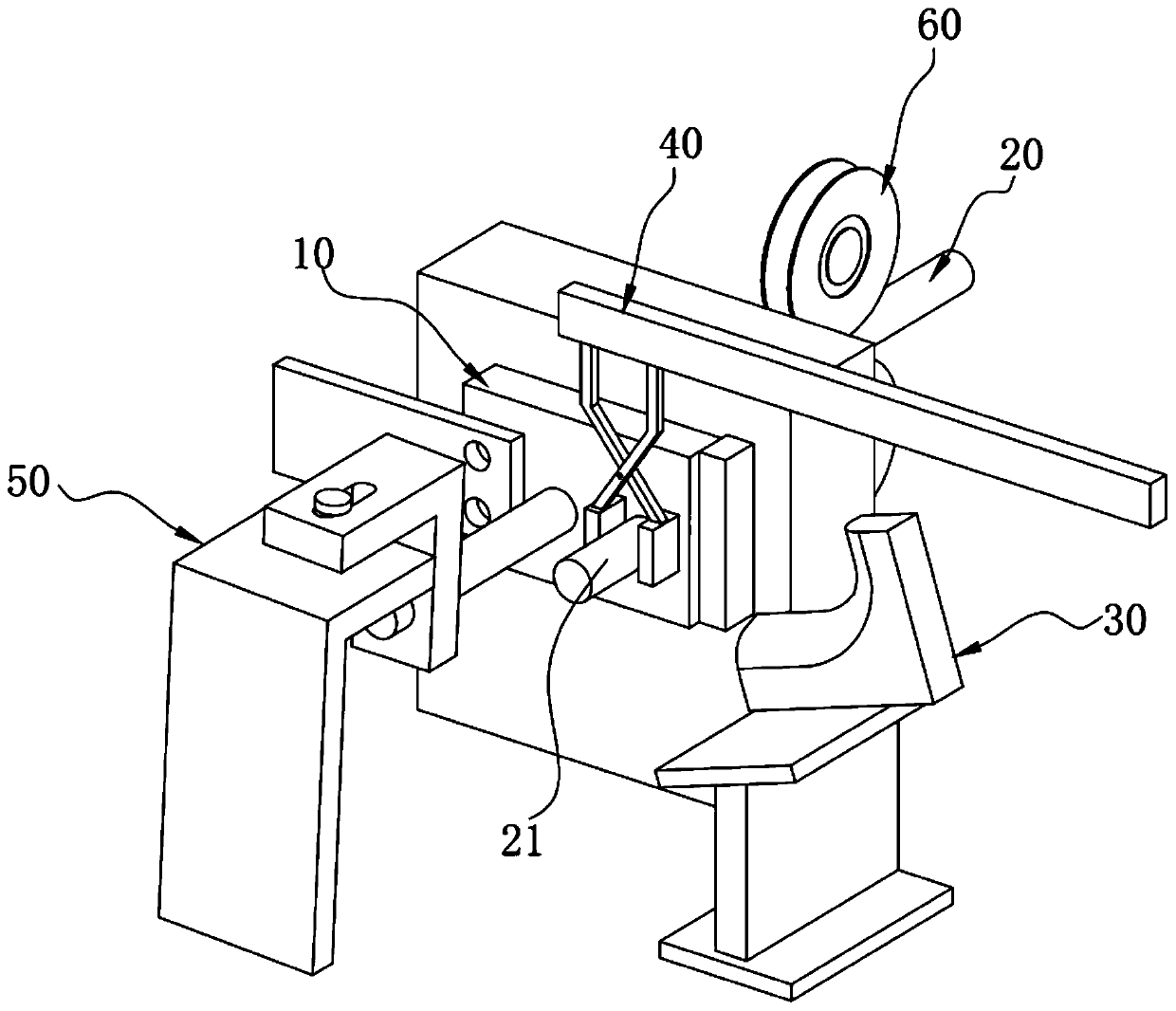
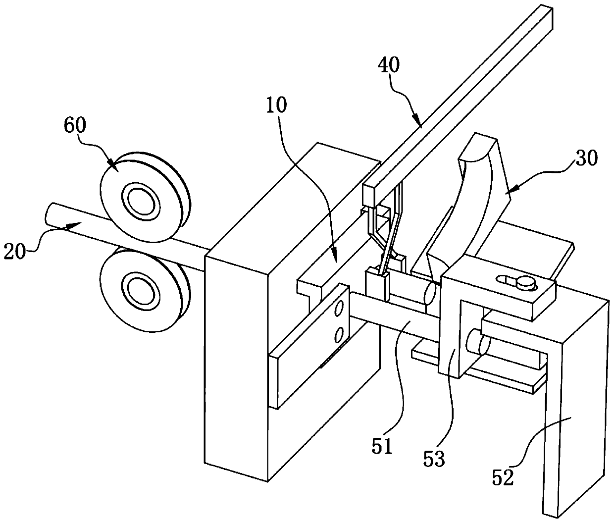
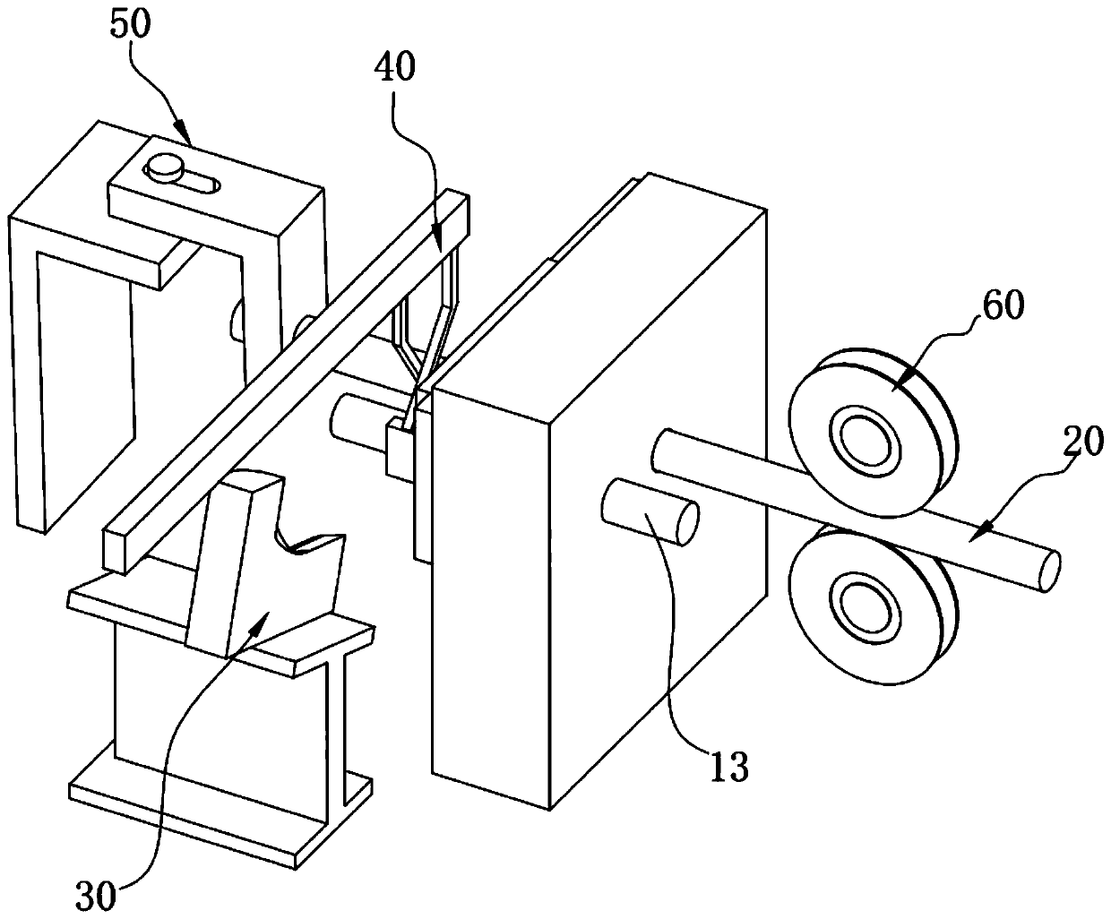
[0023] Such as Figure 1 to Figure 6 As shown, the present invention provides a material transportation and turning device, including: a shearing die 10 arranged on a frame for cutting the original material 20, the original material 20 is cut into a central axis through the shearing die 10 The material section 21 to be processed in a horizontal state; a claw hand 40 used to grasp and move the material section 21 to be processed horizontally; set on the frame and located on the side of the shearing die 10 for making the material to be processed The material diverting unit 30 whose central axis of the section 21 is transformed from a horizontal state to a vertical state; wherein the material diverting unit 30 includes a steering block 31, and a groove is formed on the steering block 31, and the groove is formed When the material section 21 to be processed moves horizontally to the steering block 31 under the drive of the claw hand 40, it abuts against the material section 21 to be processed and causes the central axis of the material section 21 to be processed from The arc-shaped guide surface 311 that transforms the horizontal state into the vertical state, attached Figure 7 The central axis of the material section 21 to be processed in is in a horizontal state, attached Figure 8 The central axis of the to-be-processed material section 21 is in a vertical state, and the material-to-be-processed section 21 can be turned over by the material turning unit 30 to be suitable for occasions with different processing requirements.
[0024] As an example of this solution, such as Figure 1 to Figure 5 As shown, the scissor mold 10 includes a fixed portion 11 fastened to the frame, and a first drive unit (not shown) is used for linear reciprocating motion at the outlet of the fixed portion 11 The end of the original material 20 is cut into the movable part 12 of the material section 21 to be processed, and a movable part 12 is arranged on the frame for removing the material section 21 to be processed after the cutting is completed. The push rod 13 pushed out by the shear hole 121 of the movable part 12, wherein the fixed part 11 is formed with a material hole 111 for conveying the raw material 20, and the movement direction of the raw material 20 in the fixed part 11 is the same as The moving direction of the movable part 12 is perpendicular, and a push rod hole 131 for setting the push rod 13 is formed on the frame, and the push rod hole 131 and the material hole 111 are arranged at the same height.
[0025] As an example of this solution, such as figure 1 with figure 2 As shown, it also includes a limiting unit 50, and the limiting unit 50 includes a device that abuts against the shearing hole 121 when the shearing hole 121 moves to the discharge port of the fixed portion 11 The limit block 51 where the original material 20 is positioned, and a fixing seat 52 installed on the frame for fastening the limit block 51, wherein the limit block 51 is fastened to the limit block 51 by a connecting block 53 The fixed seat 52 is on.
[0026] As an example of this solution, such as Figure 4 As shown, a positioning block 14 for limiting the movement stroke of the movable part 12 is fixedly provided on the frame.
[0027] As an example of this solution, such as Figure 1 to Figure 4 As shown, it also includes a conveying wheel 60 for conveying the original material 20 to the fixed portion 11, and the conveying wheel 60 is arranged symmetrically up and down.
[0028] As an example of this solution, such as Image 6 As shown, the material diverting unit 30 further includes a base 32 that allows an inclined angle between the steering block 31 and the horizontal plane, and the base 32 is fastened to the frame.
[0029] As an example of this solution, such as Image 6 As shown, the base 32 includes a bottom plate 321 horizontally arranged on the frame, an inclined plate 323 located directly above the bottom plate 321 and fastened with the steering block 31, and a bottom plate 321 connected to the bottom plate 321. And the supporting plate 322 of the inclined plate 323, wherein an acute angle exists between the inclined plate 323 and the horizontal plane.
[0030] As an example of this solution, such as Figure 5 As shown, the outlet of the material hole 111 is also fastened with a bush 112, and the outer wall of the bush 112 abuts against the hole wall of the material hole 111.
[0031] Although the embodiments of the present invention have been disclosed as above, they are not limited to the applications listed in the description and embodiments. It can be applied to various fields suitable for the present invention. For those familiar with the field, it can be easily Additional modifications are implemented, so without departing from the general concept defined by the claims and equivalent scope, the present invention is not limited to the specific details and the legends shown and described here.

PUM

no PUM

Description & Claims & Application Information

We can also present the details of the Description, Claims and Application information to help users get a comprehensive understanding of the technical details of the patent, such as background art, summary of invention, brief description of drawings, description of embodiments, and other original content. On the other hand, users can also determine the specific scope of protection of the technology through the list of claims; as well as understand the changes in the life cycle of the technology with the presentation of the patent timeline. Login to view more.

Similar technology patents

Photoelectric sensor for position of sun

InactiveCN101650173AEffective tracking range expandedSimple structure
Owner:WUHAN UNIV OF TECH

Magnetic cooling apparatus and control method thereof

ActiveUS20130180263A1simple structure
Owner:SAMSUNG ELECTRONICS CO LTD

Base for protection and display of ceramic artwork

InactiveCN107184012ASecurityAvoid manual turning
Owner:淮安市迷尔工艺品有限公司

Dual-Drivetrain of Power-Assist Vehicle

InactiveUS20100181130A1enhance uphill momentumsimple structure
Owner:CHOU WEN CHENG

Classification and recommendation of technical efficacy words

  • Simple structure
  • Avoid manual turning

Base for protection and display of ceramic artwork

InactiveCN107184012ASecurityAvoid manual turning
Owner:淮安市迷尔工艺品有限公司
Why Eureka
Try Eureka