Electrical cabinet with good heat dissipation
A heat dissipation technology for electrical cabinets, applied in the field of electrical cabinets, can solve problems such as dust ingress, and achieve the effects of good heat dissipation, good marketing value, and good practicability
- Summary
- Abstract
- Description
- Claims
- Application Information
AI Technical Summary
Problems solved by technology
Method used
Image

Examples
Embodiment Construction
[0010] The embodiments of the present invention will be further described below in conjunction with the accompanying drawings.
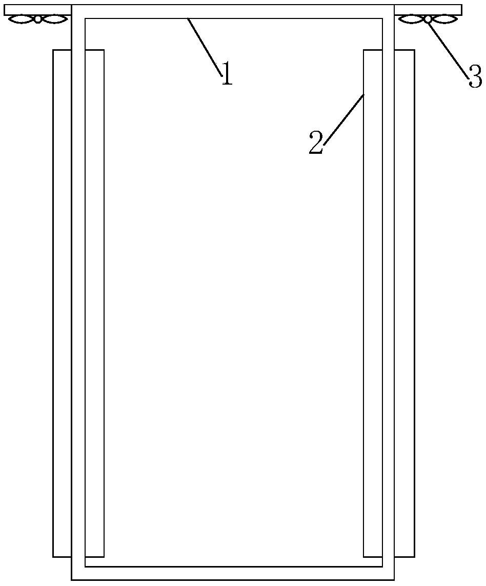
[0011] Such as figure 1 As shown, an electrical cabinet with good heat dissipation provided by this embodiment includes a cabinet body 1, and heat sinks 2 are provided on the left and right sides of the cabinet body 1, and one end of the heat sink 2 extends toward the cabinet. The other end extends to the outside of the cabinet body 1, and a ventilation duct is formed between the two adjacent cooling fins 2. The plurality of cooling fins 2 provided can facilitate heat dissipation inside the cabinet body 1 , and at the same time have good airtightness and dustproof effect.
[0012] In order to further increase the heat dissipation of the cabinet body 1 , cooling fans 3 may be provided on the left and right sides of the top of the cabinet body 1 .
[0013] Preferably, the distance between two adjacent cooling fins 2 is 1-2 cm.
[0014] The present i...
PUM
 Abstract
Description
Claims
Application Information
 - Generate Ideas
- Intellectual Property
- Life Sciences
- Materials
- Tech Scout
- Unparalleled Data Quality
- Higher Quality Content
- 60% Fewer Hallucinations
Browse by: Latest US Patents, China's latest patents, Technical Efficacy Thesaurus, Application Domain, Technology Topic, Popular Technical Reports.
© 2025 PatSnap. All rights reserved.Legal|Privacy policy|Modern Slavery Act Transparency Statement|Sitemap|About US| Contact US: help@patsnap.com