Beam-after-cable self-anchored suspension bridge design and construction method

A technology of self-anchored suspension bridge and construction method, which is applied in the direction of suspension bridge, bridge form, bridge construction, etc., can solve the problems of self-anchored suspension bridge span increase, etc., and achieve the effects of improving competitiveness, facilitating monitoring, and clear force

Inactive Publication Date: 2019-07-05
ZHEJIANG PROVINCIAL INST OF COMM PLANNING DESIGN & RES CO LTD
View PDF5 Cites 7 Cited by
  • Summary
  • Abstract
  • Description
  • Claims
  • Application Information

AI Technical Summary

Problems solved by technology

[0007] The Chinese patents whose publication numbers are CN106149569A, CN204418031U and CN104652285A propose to adopt a tower-beam temporary anchorage device, and the temporary anchorage device is used to bear the horizontal force component of the main cable in the construction process; but as the span of the self-anchore

Method used


Image

  • Beam-after-cable self-anchored suspension bridge design and construction method
  • Beam-after-cable self-anchored suspension bridge design and construction method
  • Beam-after-cable self-anchored suspension bridge design and construction method

Examples


Example Embodiment

[0034] In order to describe the present invention in more detail, the technical solution of the present invention will be described in detail below with reference to the accompanying drawings and specific embodiments.

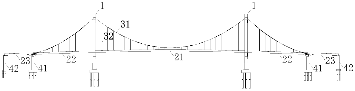
[0035] Such as figure 1 Shown here is a typical double-tower five-span self-anchored suspension bridge. The structure includes: pylon 1, pier (including auxiliary pier 41 and transition pier 42), main beam (including main span main beam 21, side span main beam 22 and anchor span main beam 23), main cable 31 and sling 32, etc.

[0036] From figure 1 The self-anchored suspension bridge is in a reasonable state. It can be seen that since the main cable 31 of the self-anchored suspension bridge is anchored to the main girder, when the main girder acts on the vertical load, the main cable 31 has a relatively large horizontal force. The component force will be borne by the main beam. The state of the structure during the construction process is not exactly the same as ...


PUM


Abstract

The invention discloses a beam-after-cable self-anchored suspension bridge design and construction method. The beam-after-cable self-anchored suspension bridge design and construction method comprisesthe steps that (1) bridge towers and bridge piles are constructed, and main beam anchoring sections are constructed; (2) temporary anchors are constructed, and temporary pintle cables are mounted; (3) main cables are erected, and the temporary pintle cables are synchronously tensioned; (4) main beam sections are hoisted, main cable saddles at the tops of the bridge towers are pushed, and the temporary pintle cables are tensioned; and (5) a whole is formed by the main beams, the temporary pintle cables are dismantled, and system transformation is completed. The beam-after-cable self-anchored suspension bridge design and construction method has the advantages that stress is clear, monitoring is convenient, and under bridge navigation is not interrupted, the construction method is simple, design and monitoring are convenient; and compared with a cable-after-beam construction method, the requirement of under bridge navigation can be guaranteed, temporary measures of full framing and temporary pile erecting in riverways with deep riverbeds and the like are avoided, the construction difficult problem of self-anchored suspension bridges located at the position with high under bridge navigation requirement and deep riverbeds is solved, and competitiveness of long span self-anchored suspension bridge is further improved.

Description

technical field [0001] The invention belongs to the technical field of bridge design and construction, and in particular relates to a design and construction method of a self-anchored suspension bridge with cables first and beams second. Background technique [0002] The biggest difference between the self-anchored suspension bridge and the traditional ground-anchored suspension bridge is that the main cable of the former is anchored on the main girder, while the main cable of the latter is anchored on the ground. Since the main cable of the self-anchored suspension bridge is anchored on the main girder, the main girder is subject to a huge horizontal component force after the bridge is completed; the main girder is gradually assembled into a whole during the construction process, and only when the main girder is integrated can it bear large Therefore, how to transfer the horizontal force of the main cable to the main girder has become one of the key technologies in the desi...

Claims


Application Information

Patent Timeline
IPC IPC(8): E01D11/02E01D21/00
CPCE01D11/02E01D21/00
Inventor 沈佳伟刘德宝张红星陈文敏
Owner ZHEJIANG PROVINCIAL INST OF COMM PLANNING DESIGN & RES CO LTD
Why Eureka
Try Eureka