Mirror lamp

A mirror and frame technology, applied in the field of mirror lights, can solve the problems of insufficient luminous flux, luminous efficiency, and poor heat dissipation, so as to improve luminous flux and brightness, avoid dark spots of light emission, and avoid power supply problems. The effect of line shadows

Pending Publication Date: 2019-07-09
XIAMEN HI LIGHT LIGHTING
View PDF0 Cites 1 Cited by
  • Summary
  • Abstract
  • Description
  • Claims
  • Application Information

AI Technical Summary

Problems solved by technology

[0003] The current mirror lights on the market mainly have two defects. The first defect is that the light source is placed inside the mirror. Since the light source is placed inside the mirror, an additional radiator is required, but the heat dissipation effect is not good, and the light loss is huge. Because the light wave is in the medium Transmission will produce reflection and scattering. Because there are two different media of glass and metal inside the frame, different degrees of attenuation of light waves are caused, resulting in the failure of the entire light to meet the requirements, and the light effect cannot meet the requirements; defect two, can be The product that realizes the 360-degree rotation of the mirror relies on the cooperation of the electrode and the spring to realize the rotation function, but due to the limitation of the structural design, the size of the electrode is too large, and the external power supply and the internal radiator need to be connected by the electrode, so the light-emitting part of the mirror when it is not shining It can be seen that there are obvious power line shadows, and there are obvious dark spots when the light is on, which is not acceptable to users, such as figure 1 shown

Method used


Image

  • Mirror lamp
  • Mirror lamp
  • Mirror lamp

Examples


Embodiment Construction

[0029] In order to further explain the technical means and effects of the present invention to achieve the intended purpose of the invention, the specific implementation, structure, features and effects of the present invention will be described in detail below in conjunction with the accompanying drawings and preferred embodiments.

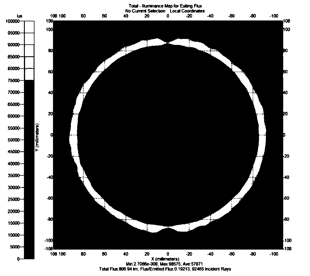
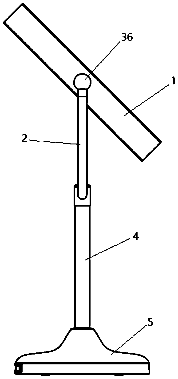
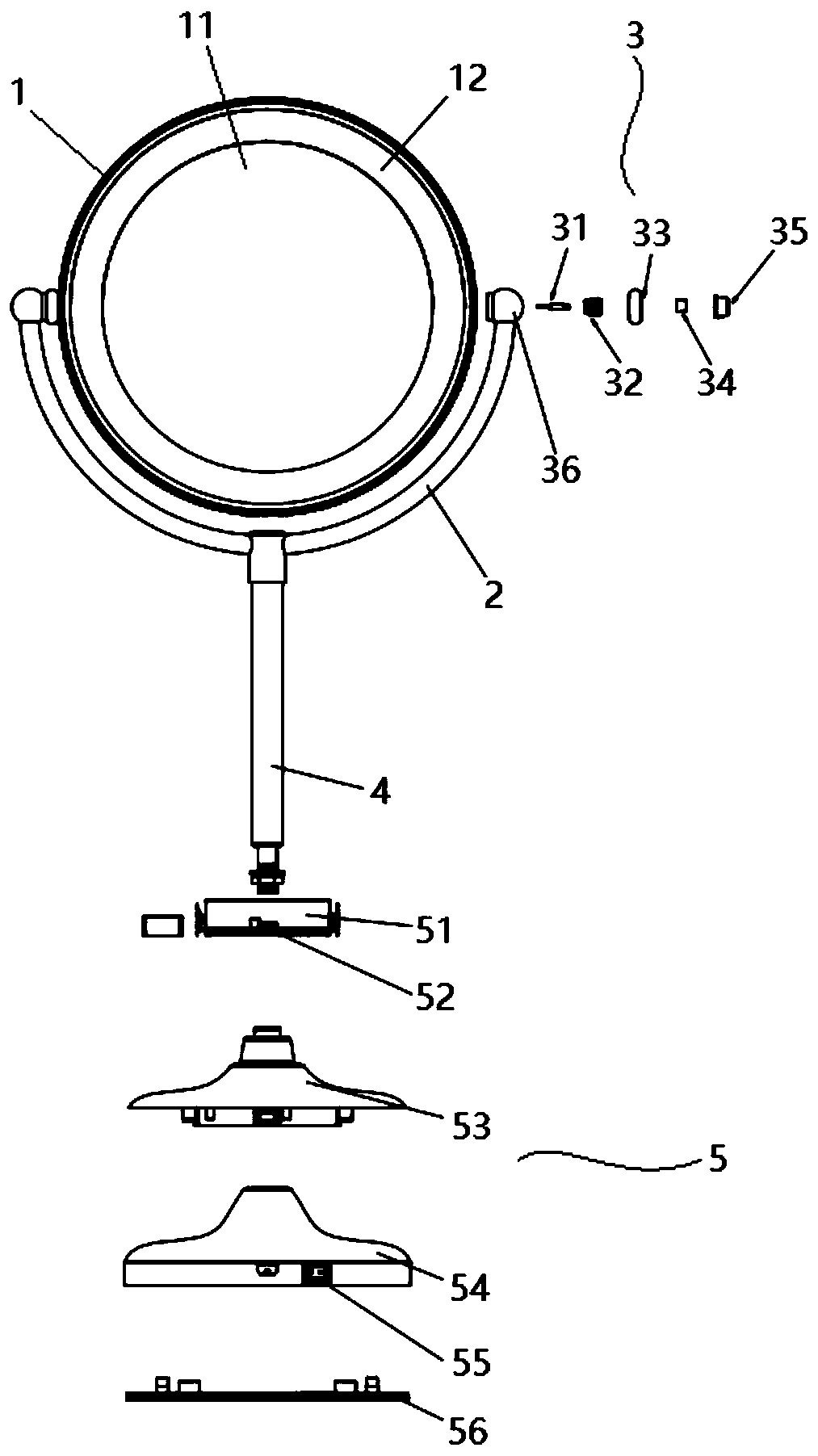
[0030] Such as Figure 2-7 As shown, a mirror lamp includes a horn bracket 2 with a built-in power cord and a picture frame 1 made of metal. The conductive assembly rotates 360°; mirrors 11 are arranged on both ends of the picture frame, one side is a 1:10 mirror, and the other side is a 1:1 mirror, and a light-emitting part 12 is arranged on the peripheral side of the mirror, and the inner wall of the picture frame is provided with The light-emitting part provides an LED light bar as a light source. One end of the conductive component is electrically connected to the power line, and the other end is electrically connected to the positive or nega...


PUM


Abstract

The invention relates to a mirror lamp. The lamp comprises a horn bracket with a built-in power cord and a mirror frame made of metal, the two ends of the mirror frame are respectively hinged on bothends of the horn bracket by a conductive assembly, and the mirror frame can conduct 360-degree rotation around the conductive assembly; at least one end surface of the two end surfaces of the mirror frame is provided with a mirror, a light-emitting portion is disposed on a circumferential side of the mirror, and the inner side wall of the mirror frame is provided with an LED lamp bar for providinga light source for the light-emitting portion. The lamp can rotate 360 degrees freely, the luminous flux is good, and the use experience is good.

Description

technical field [0001] The invention relates to the field of lighting equipment, in particular to a mirror lamp. Background technique [0002] Mirror lamp is now an emerging industry in the field of LED lighting. It perfectly combines the functions of LED lighting and mirrors. It has a broad market and is very popular among people. [0003] The current mirror lights on the market mainly have two defects. The first defect is that the light source is placed inside the mirror. Since the light source is placed inside the mirror, an additional radiator is required, but the heat dissipation effect is not good, and the light loss is huge. Transmission will produce reflection and scattering. Because there are two different media of glass and metal inside the frame, different degrees of attenuation of light waves are caused, resulting in the failure of the entire light to meet the requirements, and the light effect cannot meet the requirements; defect two, can The product that reali...

Claims


Application Information

Patent Timeline
IPC IPC(8): F21S9/02F21V13/02F21V23/06F21V29/503F21V29/89F21Y115/10F21W131/302
CPCF21S9/02F21V29/503F21V29/89F21V23/06F21V13/02F21Y2115/10F21W2131/302
Inventor 连宗山洪建顺姚志军李成桂陈建煌
Owner XIAMEN HI LIGHT LIGHTING
Why Eureka
Try Eureka