
Method for calculating DC offset coefficient of magnetic core of Flyback circuit

A DC bias and coefficient calculation technology, applied in calculation, electrical digital data processing, computer-aided design, etc., can solve the problems of not considering the change rate of magnetic flux density and the loss value can not meet the requirements, so as to achieve clear physical concept and calculation The effect of simple process

Inactive Publication Date: 2019-07-16
NANJING UNIV OF POSTS & TELECOMM
View PDF2 Cites 0 Cited by
  • Summary
  • Abstract
  • Description
  • Claims
  • Application Information

AI Technical Summary

Problems solved by technology

In addition, the SE equation only reflects the characteristics of the frequency and does not consider the rate of change of the magnetic flux density, so it can only provide accurate loss estimates in the sinusoidal case of a certain magnetic flux density, frequency and temperature range
Therefore, for magnetic components under actual complex working conditions, the loss value predicted by the SE equation cannot meet the requirements

Method used


Image

  • Method for calculating DC offset coefficient of magnetic core of Flyback circuit
  • Method for calculating DC offset coefficient of magnetic core of Flyback circuit
  • Method for calculating DC offset coefficient of magnetic core of Flyback circuit

Examples


Embodiment Construction

[0021] In order to make the content of the present invention more clearly understood, the technical solutions in the embodiments of the present invention will be clearly and completely described below in conjunction with the drawings in the embodiments of the present invention.

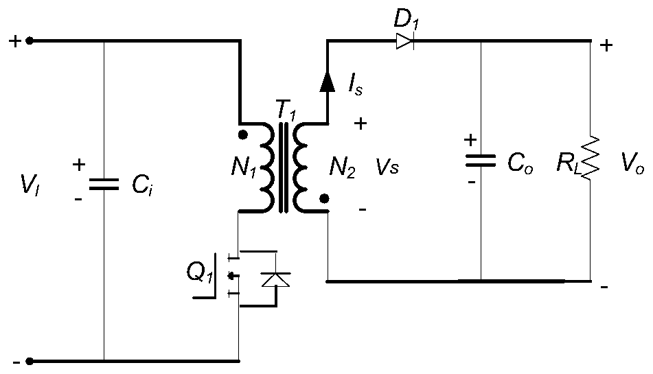
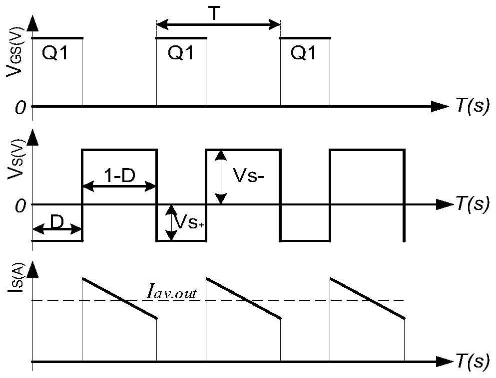
[0022] Such as figure 1 The Flyback variator shown works in CCM mode, when Q 1 When turned on, the transformer T 1 Primary winding N 1 store energy. due to T 1 The primary side of the secondary winding with the same name is opposite, so the diode D 1 It will be reverse biased and will not conduct. So when Q 1 When conducting, the voltage across the primary winding is v p (t)=V I ; when Q 1 When cut off, the primary side current I p reduced to zero. At this time, the polarity of the voltage on the winding is reversed, and the diode D 1 conduction. Q 1 At cut-off, the voltage across the secondary winding is v s (t)=-V 0 ; the relationship between input voltage and output voltage is

...


PUM


Abstract

The invention discloses a method for calculating a DC offset coefficient of a magnetic core of a Flyback circuit. Under the condition of a variation of the magnetic flux density at a duty ratio of D=0.5, by analyzing the working principle of the Flyback converter circuit, the variation rule of the DC offset coefficient of the magnetic core when the duty ratio of the Flyback converter changes is calculated. The method has the advantages of clear physical concept and simple calculation process, and can effectively predict the DC offset coefficient of the core material in the output inductor of the Flyback converter under different duty ratios.

Description

technical field [0001] The invention relates to a method for calculating a DC bias coefficient of a magnetic core of a Flyback circuit, in particular to a method for calculating the DC bias coefficient under different duty cycle conditions. Background technique [0002] Ferrite cores are widely used in switching converters due to their high resistivity and low core loss characteristics. Different topological structures require different excitation waveforms, which bring significant difficulties to the estimation of magnetic loss of non-sinusoidal high-frequency excitation power, and the magnetic flux density, frequency, duty cycle, temperature, excitation voltage and DC bias Such working conditions will have a direct impact on the power loss of magnetic components, so the modeling of core loss is extremely difficult. [0003] In the practical application of core loss prediction, the Steinmetz (SE) equation based on experimental data fitting is commonly used. The classic SE...

Claims


Application Information

Patent Timeline
IPC IPC(8): G01R27/26G06F17/50
CPCG01R27/2688G06F30/20
Inventor 田家良崔林威王奔周岩张宇飞
Owner NANJING UNIV OF POSTS & TELECOMM
Features
  • Generate Ideas
  • Intellectual Property
  • Life Sciences
  • Materials
  • Tech Scout
  • Unparalleled Data Quality
  • Higher Quality Content
  • 60% Fewer Hallucinations
Learn More