Check patentability & draft patents in minutes with Patsnap Eureka AI!

Limited tube moving machine

A technology of displacement tube and frame, applied in the direction of crane, traveling mechanism, trolley crane, etc., can solve the problems of inversion, tube transfer machine hitting both ends of gantry frame, poor braking effect, etc., and achieve the effect of preventing hard collision.

Inactive Publication Date: 2019-07-23
山东省田庄煤矿有限公司
View PDF5 Cites 0 Cited by
  • Summary
  • Abstract
  • Description
  • Claims
  • Application Information

AI Technical Summary

Problems solved by technology

The existing limited-displacement tube machine has the following problems during use: First, the tube transfer machine is set on the gantry. During use, due to the inertia of motion, the problem that the tube transfer machine hits the two ends of the gantry frame is prone to occur, especially the pipe transfer machine. Frame, the frame is equipped with motors, reels and other components, and the impact of the frame is likely to affect the normal operation of other components; secondly, during the lifting process of the pipe transfer machine lifting the idler tube, the wire rope on the reel is likely to be in the middle of the support when braking. Under the gravity of the roller tube, reverse rotation occurs, and the braking effect is not good

Method used


Image

  • Limited tube moving machine
  • Limited tube moving machine
  • Limited tube moving machine

Examples


Embodiment Construction

[0017] The present invention will be further described in detail below in conjunction with the accompanying drawings and specific embodiments.

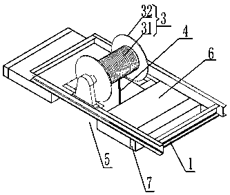
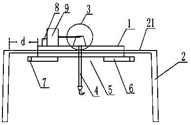
[0018] attached figure 1 And attached figure 2 It is a specific embodiment of the present invention. A displacement-limiting tube machine, comprising a frame (1), the frame (1) is slidably arranged on the beam (21) of the gantry (2), and the frame (1) is provided with a motor-driven A reel (3), the reel (3) is wound with a steel wire rope (4), and the position of the frame (1) corresponding to the reel (3) is provided with an avoidance area for avoiding the steel wire rope (4) (5), the bottom of the frame (1) is provided with a slide plate (6) for adjusting the size of the avoidance area (5), the slide plate (6) can slide horizontally along the frame (1), and the slide plate (6) Limiting elastic pads (7) are provided on the sides near the two ends of the beam of the gantry (2);

[0019] Both ends of the frame (1) along the extens...


PUM


Abstract

The invention discloses a limited tube moving machine. The limited tube moving machine is used for moving a carrier roller tube in a carrier roller production process, the limited tube moving machinecomprises a machine frame, wherein the machine frame is arranged on a cross beam of a portal frame in a sliding mode, a winding drum driven by a motor is arranged on the machine frame, a steel wire rope is wound on the winding drum, an receding area for receding the steel wire rope is arranged at the position, corresponding to the winding drum, of the machine frame, sliding plates for adjusting the size of the receding area are arranged at the bottom of the machine frame, the sliding plates can horizontally slide along the machine frame, elastic cushions are arranged on the side surfaces, close to the two ends of the portal frame cross beam, of the sliding plates, distance detection devices used for detecting the distance between the machine frame and the portal frame end part are arrangedat the two ends, in the extending direction of the cross beam of the portal frame, of the machine frame, the distance detection devices transmit detected distances d to a controller, and the controller controls the sliding plate to move in the direction away from the winding drum according to the feedback. The limited tube moving machine can effectively prevent the tube moving machine frame fromcolliding with the portal frame and protect the tube moving machine.

Description

technical field [0001] The invention relates to a mobile device for producing idler rollers, in particular to an idler tube displacement limiting machine. Background technique [0002] The idler is an important part of the conveying equipment. In the production process of the idler, one of the processes is to cut the long idler tube into a short idler tube. During the lifting process of the long idler tube and the short idler tube, there will be A limit displacement tube machine is used. The existing limited-displacement tube machine has the following problems during use: First, the tube transfer machine is set on the gantry. During use, due to the inertia of motion, the problem that the tube transfer machine hits the two ends of the gantry frame is prone to occur, especially the pipe transfer machine. Frame, the frame is equipped with motors, reels and other components, and the impact of the frame is likely to affect the normal operation of other components; secondly, duri...

Claims


Application Information

Patent Timeline
IPC IPC(8): B66C19/00B66C11/00B66C7/16B66C9/10B66C13/48B66C13/16
CPCB66C7/16B66C9/10B66C11/00B66C13/16B66C13/48B66C19/00
Inventor 夏文营张烜赫
Owner 山东省田庄煤矿有限公司
Features
  • R&D
  • Intellectual Property
  • Life Sciences
  • Materials
  • Tech Scout
  • Unparalleled Data Quality
  • Higher Quality Content
  • 60% Fewer Hallucinations
Learn More