Check patentability & draft patents in minutes with Patsnap Eureka AI!

Multimode Clutch

A clutch and control ring technology, applied to clutches, one-way clutches, mechanical equipment, etc., can solve the problems of inner ring slipping, low locking torque, multi-mode clutch failure, etc., and achieve the effect of simple structure

Active Publication Date: 2021-01-05
江西鼎盛新材料科技有限公司
View PDF5 Cites 0 Cited by
  • Summary
  • Abstract
  • Description
  • Claims
  • Application Information

AI Technical Summary

Problems solved by technology

The locking torque of the multi-mode clutch with this structure is relatively low, and there is a risk of inner ring slipping; when the roller is in the neutral position and the inner ring can rotate clockwise and counterclockwise, due to the friction between The deflection of the inner ring caused by force and external factors makes there is a risk that the rollers will suddenly enter the locking position and cause the multi-mode clutch to fail

Method used


Image

  • Multimode Clutch
  • Multimode Clutch
  • Multimode Clutch

Examples


Embodiment 1

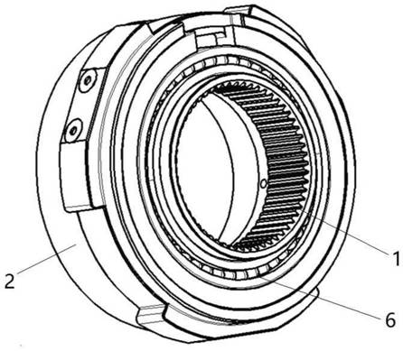
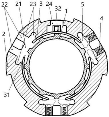
[0016] A multi-mode clutch such as figure 1 , figure 2 , as shown in Figure 3(a) and Figure 3(b), including the inner ring 1, the outer ring 2 and the control ring 3, the inner ring 1, the outer ring 2 and the control ring 3 are all cylindrical sleeve structures, the inner ring 1 There are several uniformly distributed rectangular spline teeth 11 on the outer surface, the inner surface of the inner ring 1 and the outer surface of the outer ring 2 are all spline structures, and the inner surface of the outer ring 2 is provided with three uniformly distributed spline teeth. Avoidance groove 21, the bottom of avoidance groove 21 is provided with two radial through-holes 22, is provided with the locating seat 4 that spring is installed in the radial through-hole 22 and locating seat 4 can radially expand and contract, and avoiding groove 21 is parallel to the axis. There are axial through grooves 23 of symmetrical cylindrical structure on both sides of the direction. The axial t...

Embodiment 2

[0019] A multi-mode clutch, its structure is similar to that of the multi-mode clutch in Embodiment 1, the difference is that the number of escape grooves on the outer ring is four, the number of windows on the control ring is four, and the number of windows on the outer ring is four. A ball bearing is arranged at one end between the ring and the inner ring, and the ball bearing is opposite to the end face of the control ring.


PUM


Abstract

The invention provides a multi-mode clutch. A plurality of receding grooves which are uniformly distributed are formed in the inner side surface of an outer ring, two radial through holes are formed in the bottoms of the receding grooves, positioning seats provided with springs are arranged in the radial through holes, and axial through grooves with cylindrical structures are symmetrically formedin the two sides, parallel to the axial direction, of the receding grooves; blocking blocks are in clamping connection with the axial through grooves in a matched mode, the sides, facing the positioning seats, of the blocking blocks are in contact with the positioning seats, a limiting groove is formed in one end surface of the outer ring, a plurality of uniformly distributed windows are formed inthe outer side surface of a control ring, and a driving block which protrudes outwards is arranged on one end surface of the control ring in parallel; and the outer ring, the control ring and an inner ring are sequentially sleeved together in a clearance mode from outside to inside, the windows of the control ring are in one-to-one correspondence with the receding grooves of the outer ring, and the driving block of the control ring is arranged in the limiting groove of the outer ring. According to the multi-mode clutch, the structure is simple, the locking direction of the inner ring is adjusted to enable the multi-mode clutch to have three working modes, and meanwhile, the slippage of the inner ring can be avoided.

Description

technical field [0001] The invention relates to a multimode clutch. Background technique [0002] At present, in a hybrid transmission or an automatic transmission of an automobile, a multi-mode clutch is often required to prevent or allow a certain part in the transmission to rotate. At present, multi-mode clutches in engineering applications mainly include rollers, roller retaining springs, control rings, inner rings, and outer rings. The relative position between them depends on the friction force when the rollers and the inner ring and the outer ring are in contact at the same time to prevent or allow the inner ring to rotate. The locking torque of the multi-mode clutch with this structure is relatively low, and there is a risk of inner ring slipping; when the roller is in the neutral position and the inner ring can rotate clockwise and counterclockwise, due to the friction between The deflection of the inner ring caused by force and external factors makes there is a r...

Claims


Application Information

Patent Timeline
Patent Type & Authority Patents(China)
IPC IPC(8): F16D41/08F16D41/069
CPCF16D41/069F16D41/084
Inventor 翟光勇钟发平魏波宋东芳阳华萍章金乐韩启锋庞雷保孙哲浩
Owner 江西鼎盛新材料科技有限公司
Features
  • R&D
  • Intellectual Property
  • Life Sciences
  • Materials
  • Tech Scout
  • Unparalleled Data Quality
  • Higher Quality Content
  • 60% Fewer Hallucinations
Learn More