A logistics transport handling device
A handling device and logistics technology, which is applied in the directions of transportation and packaging, transportation of objects, and arrangement of loading and unloading vehicles, which can solve the problems of transporting items that cannot be on the ground to the vehicle.
- Summary
- Abstract
- Description
- Claims
- Application Information
AI Technical Summary
Problems solved by technology
Method used
Image


Examples
specific Embodiment approach 1
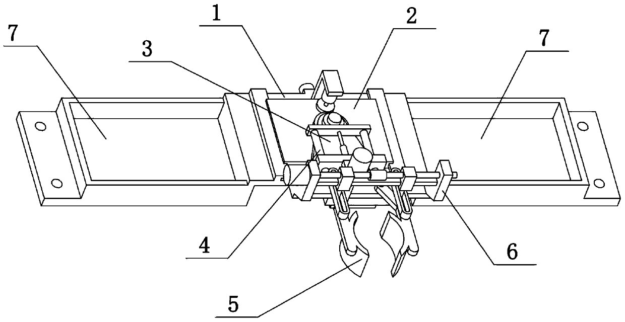
[0034] Combine below Figure 1-14 To illustrate this embodiment, the present invention relates to the field of logistics transportation, more specifically, a logistics transportation and handling device, including a base 1, a moving seat 2, a rotating seat 3, a front extension frame 4, a transport frame 5, and a opening and closing control mechanism 6 and the storage box 7, the present invention can lift the goods after being clamped, and can carry the goods to the two storage boxes 7 and place them.
[0035] The moving seat 2 is slidably connected to the upper end of the base 1, the moving seat 2 and the base 1 are matched by threads, the rotating seat 3 is connected to the upper end of the moving seat 2 in rotation, the rotating seat 3 and the moving seat 2 are meshed for transmission, and the front extension frame 4 Slidingly connected to the upper end of the rotating seat 3, the carrier frame 5 is slidably connected to the upper end of the front extension frame 4, the carr...
specific Embodiment approach 2
[0037] Combine below Figure 1-14 To illustrate this embodiment, the base 1 includes a bottom plate 1-1, a rectangular hole 1-2, a slide rail 1-3, a convex plate 1-4, a lead screw I1-5 and a motor I1-6, and the upper end of the bottom plate 1-1 The left and right ends are fixedly connected with slide rails 1-3, the upper middle of the bottom plate 1-1 is provided with a rectangular hole 1-2, the front and rear sides of the middle of the bottom plate 1-1 are fixedly connected with convex plates 1-4, screw The front and rear ends of I1-5 are respectively rotatably connected to two convex plates 1-4, the motor I1-6 is fixedly connected to one of the convex plates 1-4, and the output shaft of the motor I1-6 is fixedly connected to the lead screw I1- 5 at one end. When the output shaft of the motor I1-6 rotates, it can drive the screw I1-5 to rotate around its own axis.
specific Embodiment approach 3
[0039] Combine below Figure 1-14 To illustrate this embodiment, the moving seat 2 includes a front and rear moving plate 2-1, a central shaft 2-2, a motor frame 2-3, a motor II2-4, a gear I2-5, a limit ring 2-6 and a lower convex seat 2-7, the front and rear moving plate 2-1 is slidably connected between the two slide rails 1-3, the lower side of the front and rear moving plate 2-1 is fixedly connected with the lower convex seat 2-7, and the lower convex seat 2-7 is slidably connected On the rectangular hole 1-2, the leading screw I1-5 is matched with the lower convex seat 2-7 by threads, and the center of the upper side of the forward and backward moving plate 2-1 is fixedly connected with the central axis 2-2, and the center axis 2-2 The upper end is fixedly connected with the limit ring 2-6, the rear side of the front and rear moving plate 2-1 is fixedly connected with the motor frame 2-3, the motor frame 2-3 is fixedly connected with the motor II2-4, and the lower output ...
PUM
 Abstract
Description
Claims
Application Information
 - R&D
- Intellectual Property
- Life Sciences
- Materials
- Tech Scout
- Unparalleled Data Quality
- Higher Quality Content
- 60% Fewer Hallucinations
Browse by: Latest US Patents, China's latest patents, Technical Efficacy Thesaurus, Application Domain, Technology Topic, Popular Technical Reports.
© 2025 PatSnap. All rights reserved.Legal|Privacy policy|Modern Slavery Act Transparency Statement|Sitemap|About US| Contact US: help@patsnap.com