Novel separate rail tray cable bridge frame

A cable tray and tray-type technology, applied in the direction of electrical components, etc., can solve the problems of no separation partition, cable burnt, cable tray without flame-retardant partition, etc., to ensure the safety of life and property, avoid mutual interference, and avoid the spread of fire Effect

Pending Publication Date: 2019-10-08
天津金中马电气成套设备有限公司
0 Cites 0 Cited by

AI-Extracted Technical Summary

Problems solved by technology

[0003] Most of the existing cable trays have a straight-through structure inside, and generally there is no separation partition, and all the cables inside are mixed together, which is easy to cause fire and other disasters. In addition, most o...

Method used

During work, first fixed plate 3 is fixed on the suitable position of roof by the expansion bolt that the second through hole 11 inside reserves, then by the cooperation of fastening nut 7 the second on two bridge frame bodies 1 The fixed plate 4 is set on the surface of the threaded column 6 and fixed, and then the cables are classified and placed inside the bridge body 1, and the various cables are separated by the separation partition 8, and the separation partition 8 is provided. The cables inside the bridge body 1 are grouped so that the cables belonging to the same transmission type are together, so as to avoid mutual interference between different types of cables, and at the same time effectively avoid the occurrence of fire. 10. Separate the cables into sections, so that if a fire occurs, the flame-retardant partition 10 can effectively block the spread of the fire, avoid the spread of the fire inside the cable tray, and then effectively control the fire. , can effectively guarantee the safety of life and property, and at the same time, the inner surface of the bridge body 1 and both sides of the separation partition 8 are provided with an insulating layer 14 made of polyethylene, and the insulating layer 14 made of polyethylene has good insulating properties. Effective insulation treatment can be carried out between the cable, the bridge body 1 and the separating partition 8, thereby avoiding electrification on the surface of the bridge body 1, and effectively protecting people around.
Wherein, both sides of flame-retardant dividing plate 10 and the surface of insulating layer 14 are all fixedly provided with flame-retardant layer 15, and flame-retardant layer 15 adopts rock wool to make, and the flame-retardant layer 15 that rock wool is made has good Flame retardancy, if a certain section of the cable leaks and catches fire, the flame retardant layer 15 can effectively block the fire and avoid t...

Abstract

The invention discloses a novel separate rail tray cable bridge frame comprising two bridge frame bodies, two bridge frame cover plates and a plurality of first fixing plates. The bridge frame cover plates are engaged and connected on the top end of the bridge frame bodies. A plurality of second fixing plates are fixedly arranged at the bottom of the two sides of the bridge frame bodies. A plurality of second fixing plates are equally spaced on the two sides of the bridge frame bodies. A first through hole is arranged in the top of each of a plurality of first fixing plates. A screw column isfixedly arranged in the middle of the bottom end of each of a plurality of first fixing plates. The separation partition plate is arranged and the cables inside the bridge frame bodies are grouped, and the cables of the same transmission type are grouped together so as to avoid the mutual interference between the cables of different types. The flame-retardant separation plate can effectively blockthe spread of the fire, avoid the spread of the fire inside the cable bridge frame and then can effectively control the fire and can effectively ensure the safety of life and property.

Application Domain

Electrical apparatus

Technology Topic

Cable trayEngineering

Image

  • Novel separate rail tray cable bridge frame
  • Novel separate rail tray cable bridge frame
  • Novel separate rail tray cable bridge frame

Examples

  • Experimental program(1)

Example Embodiment

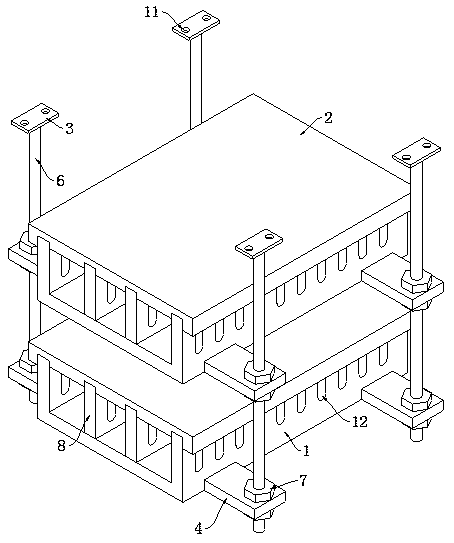
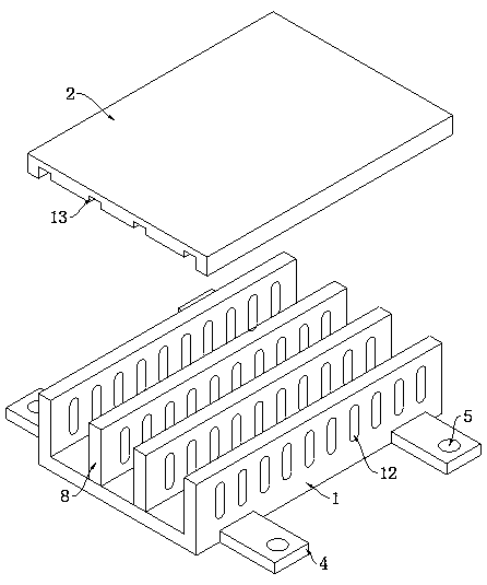
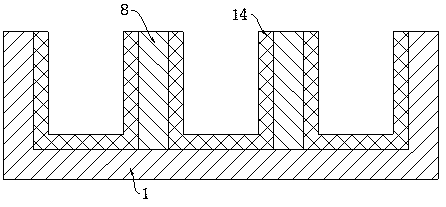
[0021] Example: such as figure 1 , figure 2 , image 3 , Figure 4 , Figure 5 with Image 6 As shown, a new type of track-dividing tray-type cable bridge of the present invention includes two bridge bodies 1, two bridge cover plates 2 and a plurality of first fixing plates 3. The bridge cover plates 2 are snap-connected to the bridge body 1 At the top, the bottoms of both sides of the bridge body 1 are fixed with a number of second fixing plates 4, and a number of second fixing plates 4 are equally spaced on both sides of the bridge body 1. The top ends of the plurality of first fixing plates 3 are A first through hole 5 is opened, and the middle of the bottom ends of a plurality of first fixing plates 3 are fixed with threaded posts 6, and a plurality of threaded posts 6 are respectively inserted into the corresponding first through holes 5, and a plurality of second fixing plates Both the top and bottom ends of 4 are provided with fastening nuts 7, and a number of fastening nuts 7 are respectively screwed to the outer surface of a number of threaded columns 6, and two separation partitions 8 are fixed at equal intervals inside the bridge body 1. Two separating partitions 8 are arranged in parallel with the two sides of the bridge body 1, and both sides of the inner cavity of the bridge body 1 and both sides of the two separating partitions 8 are provided with slots 9, one of the two corresponding slots 9 The same flame-retardant partition 10 is fixedly inserted between them.
[0022] Among them, the tops of several first fixing plates 3 are provided with two second through holes 11, and the two second through holes 11 are respectively located at the two ends of the first fixing plate 3, and the insides of the two are movably inserted with For the expansion bolt, the second through hole 11 is provided and the expansion bolt is reserved inside the second through hole 11, so that the first fixing plate 3 and the roof can be fixedly connected by the expansion bolt, thereby facilitating the fixing of the entire device.
[0023] Among them, the two sides of the bridge body 1 and the sides of the four separation partitions 8 are provided with ventilation holes 12, there are several ventilation holes 12, and the several ventilation holes 12 are distributed horizontally and equally. The cables are used for power transmission. When heat is generated, the ventilation holes 12 can ensure the air flow inside the bridge body 1 and facilitate the heat dissipation of the cables inside the bridge body 1.
[0024] Among them, the bottom ends of the two bridge cover plates 2 are each provided with four clamping slots 13, and the four clamping slots 13 are respectively provided with the two sides of the top of the bridge body 1 and the top of the two separating partitions 8, so as to facilitate the alignment. The bridge body 1 and the bridge cover plate 2 are snap-fittedly connected, thereby facilitating effective protection of the top end of the bridge body 1.
[0025] Among them, the inner surface of the bridge body 1 and the two sides of the separation partition 8 are fixed with an insulating layer 14. The insulating layer 14 is made of polyethylene. The insulating layer 14 made of polyethylene has good insulation performance and can be used for cables. Effective insulation treatment is performed between the bridge body 1 and the separation partition 8 to prevent the surface of the bridge body 1 from being charged, and effectively protect the surrounding people.
[0026] Among them, both sides of the flame-retardant separator 10 and the surface of the insulating layer 14 are fixedly provided with a flame-retardant layer 15 which is made of rock wool. The flame-retardant layer 15 made of rock wool has good flame retardancy. In this way, if a certain section of the cable is on fire due to leakage, the flame-retardant layer 15 can effectively block the fire and prevent the fire from spreading.
[0027] When working, first fix the first fixing plate 3 in the proper position on the roof through the expansion bolts reserved inside the second through hole 11, and then fix the second fixing plates 4 on the two bridge bodies 1 through the cooperation of the fastening nuts 7 Put it on the surface of the threaded column 6 and fix it, then sort the cables and place them inside the bridge body 1, and separate the various cables by the separation partition 8. The internal cables are grouped so that the cables belonging to the same transmission type are put together, so as to avoid mutual interference between different types of cables, and at the same time, it can also effectively avoid the occurrence of fire. In addition, the flame-retardant partition 10 is used to prevent The cables are divided into sections, so that if a fire occurs, the flame-retardant partition 10 can effectively block the spread of the fire, avoid the spread of the fire inside the cable tray, and then can effectively control the fire. At the same time, the inner surface of the bridge body 1 and the two sides of the separation partition 8 are provided with an insulating layer 14 made of polyethylene. The insulating layer 14 made of polyethylene has good insulation performance and can be used for cables. Effective insulation treatment is performed between the bridge body 1 and the separation partition 8 to prevent the surface of the bridge body 1 from being charged, and effectively protect the surrounding people.

PUM

no PUM

Description & Claims & Application Information

We can also present the details of the Description, Claims and Application information to help users get a comprehensive understanding of the technical details of the patent, such as background art, summary of invention, brief description of drawings, description of embodiments, and other original content. On the other hand, users can also determine the specific scope of protection of the technology through the list of claims; as well as understand the changes in the life cycle of the technology with the presentation of the patent timeline. Login to view more.

Similar technology patents

Network filter having expansion function

Owner:博众优浦(常熟)汽车部件科技有限公司

Method for realizing backup and load shared equally based on proxy of address resolution protocol

InactiveCN100359875CAvoid waste of forwarding capacity and bandwidthavoid mutual interference
Owner:苏师大半导体材料与设备研究院(邳州)有限公司

Forming method for semiconductor device

ActiveCN110875254Aeasy to receiveavoid mutual interference
Owner:CHANGXIN MEMORY TECH INC

Rapidly-deployable parabolic antenna unit mechanism

Owner:NO 54 INST OF CHINA ELECTRONICS SCI & TECH GRP

Integrated device for experimental rat water maze experiment

PendingCN110574706Aavoid mutual interferenceeasy to distinguish
Owner:TIANJIN KANGTING BIOLOGICAL ENG GRP CO LTD

Classification and recommendation of technical efficacy words

  • avoid fire
  • avoid mutual interference

Intelligent suspension type stereo garage and work method thereof

ActiveCN104831966Aavoid firereduce storage time
Owner:JIANGSU QIANYI IND

System and method for monitoring cable

InactiveCN104596572Aavoid fireReduce the difficulty of supervision
Owner:WUHU YANGYU ELECTROMECHANICAL TECH DEV

Retractable hatch container and floating element equipotential connection system

ActiveCN102991895Aavoid fire
Owner:河北珠峰仪器仪表设备有限公司

Tunnel cable fire monitoring device and early warning method

PendingCN110867042Aavoid firereduce losses
Owner:CHONGQING HEHANG TECH

Safe smoking device

InactiveCN103181619AKeep the environment tidyavoid fire
Owner:刘书庆 +1

Multi-channel numerical control system and multi-channel control method thereof

InactiveCN103809523AImprove data securityavoid mutual interference
Owner:BEIJING INST OF COMP TECH & APPL +1
Why Eureka
Try Eureka