Power conversion device

A technology of power conversion devices and capacitors, which is applied in the direction of output power conversion devices, electrical components, and structural parts of conversion equipment, etc., which can solve the problems of increased size, inability to improve vehicle space efficiency and layout, and improve wiring efficiency Effect

Active Publication Date: 2019-10-11
HONDA MOTOR CO LTD
View PDF13 Cites 0 Cited by
  • Summary
  • Abstract
  • Description
  • Claims
  • Application Information

AI Technical Summary

Problems solved by technology

As a result, the overall size of the drive unit in the vertical direction of the vehicle i

Method used


Image

  • Power conversion device
  • Power conversion device
  • Power conversion device

Examples


Example Embodiment

[0026] Hereinafter, an embodiment of the power conversion device of the present invention will be described with reference to the drawings.

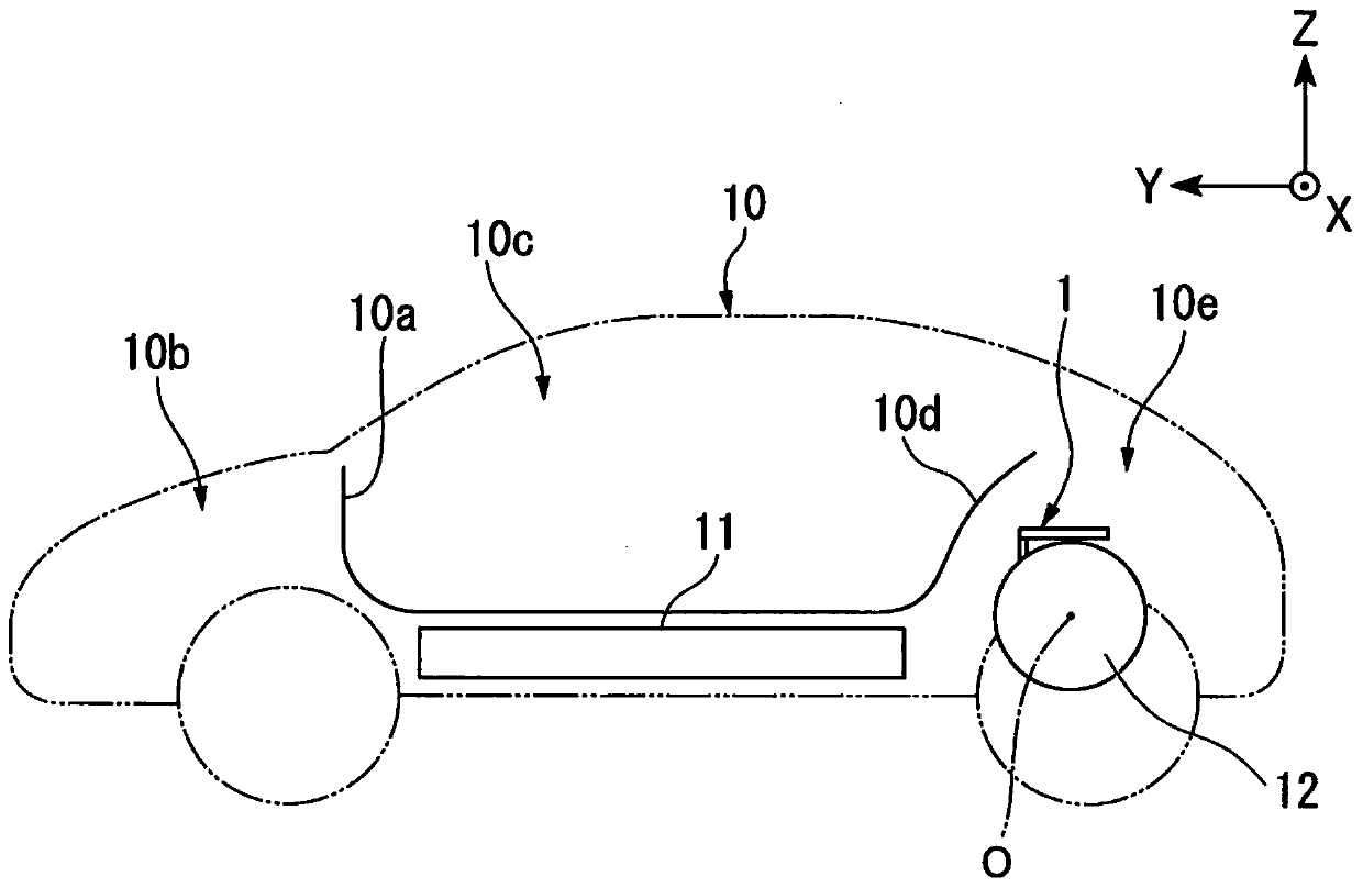
[0027] The power conversion device of this embodiment controls the power transfer between the motor and the battery. For example, the power conversion device is mounted on an electric vehicle or the like. Electric vehicles include electric vehicles, hybrid vehicles, and fuel cell vehicles. Electric vehicles are driven by batteries as a power source. Hybrid vehicles use batteries and internal combustion engines as power sources for driving. Fuel cell vehicles use fuel cells as a power source for driving.

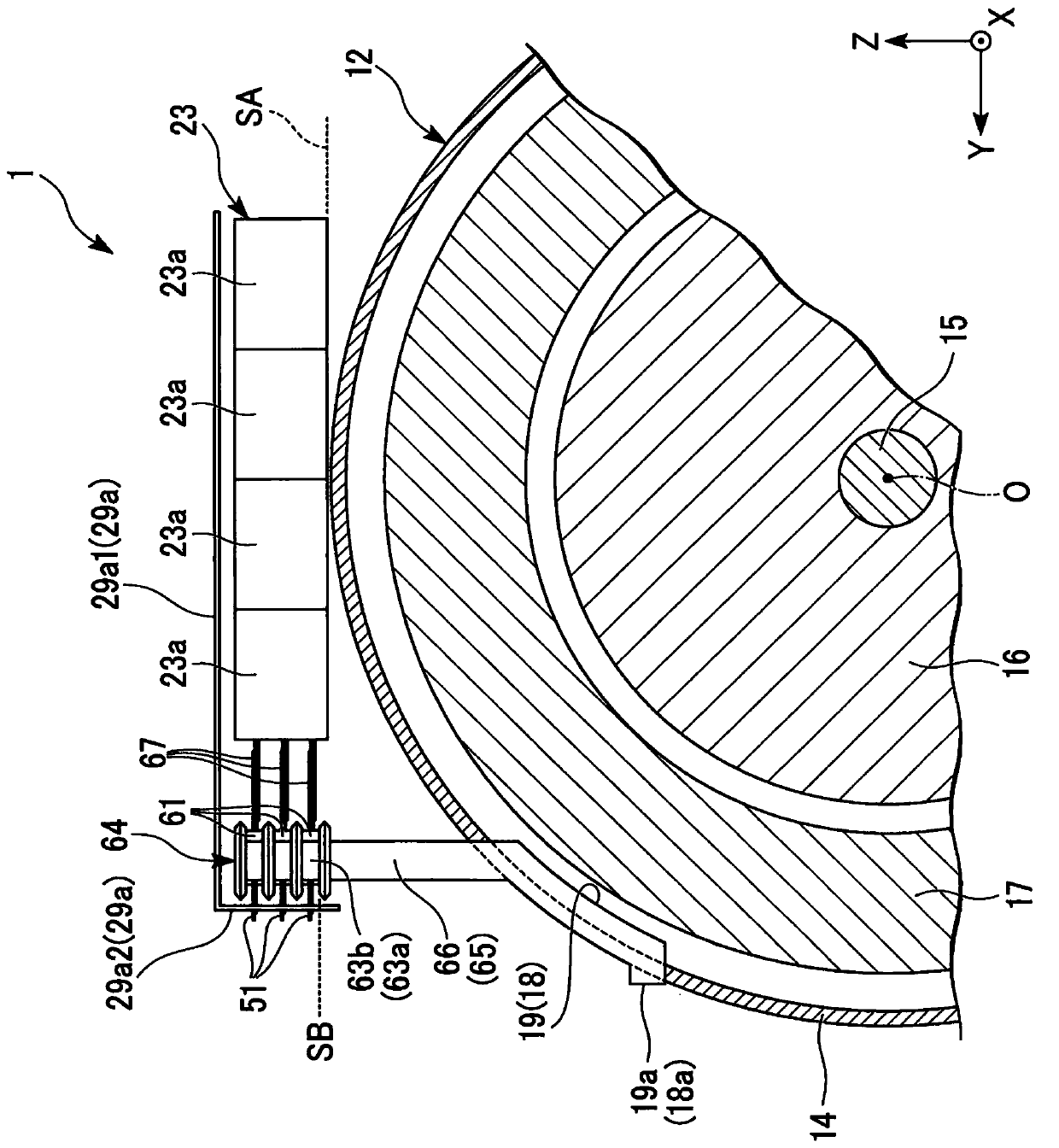
[0028] figure 1 It is a diagram schematically showing the structure of the power conversion device 1 according to the embodiment of the present invention, and is a diagram showing a part of the electric motor 12 when viewed from the axial direction of the electric motor 12 and a part of the power conversion device 1 is omitted. figure 2 ...


PUM


Abstract

The invention provides a power conversion device capable of improving wiring efficiency and improving space efficiency and layout characteristics when it is attached to another device. The power conversion device (1) includes a plurality of semiconductor modules (61), a capacitor unit (23), and a conductor group (67) including a positive electrode bus bar and a negative electrode bus bar. When viewed from a direction in parallel to a placement surface (SA), the plurality of semiconductor modules (61) and the capacitor unit (23) are arranged to overlap each other in the orthogonal direction orthogonal to the placement surface (SA). The conductor group (67) extends along a direction in parallel to the placement surface (SA) in a range in which the positions of the plurality of semiconductormodules (61) and the capacitor unit (23) overlap each other in the orthogonal direction in a state in which the positive electrode bus bar and the negative electrode bus bar face each other, and connects the semiconductor modules (61) and the capacitor unit (23).

Description

technical field [0001] The present invention relates to power conversion devices. Background technique [0002] Conventionally, a drive unit for a vehicle has been known, which has a drive unit housing for accommodating a generator and an electric motor, and a power control unit mounted in the drive unit housing (for example, refer to JP-A-2016-140198 ). In this vehicle drive unit, the power control unit includes two inverters respectively connected to a generator and a motor, a control unit for controlling the two inverters, a current sensor, and the like in a unit case. The outer shape of the drive unit case is formed in a cylindrical shape, and the drive unit case is arranged such that the axial direction becomes the vehicle width direction. The outer shape of the unit case is formed in a box shape, and the unit case is arranged to be placed on the upper surface of the drive device case in the vertical direction of the vehicle. [0003] However, according to the vehicl...

Claims


Application Information

Patent Timeline
IPC IPC(8): H02M7/00
CPCH02M7/003
Inventor 采女贵宽
Owner HONDA MOTOR CO LTD
Why Eureka
Try Eureka