Supercharge Your Innovation With Domain-Expert AI Agents!

Accompanying clamps and clamping units for shaft products

A fixture and product technology, applied in the direction of clamping, manufacturing tools, metal processing machinery parts, etc., can solve the problems of circumferential rotation error, difficulty in realizing circumferential clamping and positioning, and different positioning references, so as to improve efficiency and accuracy, The effect of preventing circumferential rotation and preventing damage

Active Publication Date: 2020-06-05
CHONGQING UNIV
View PDF10 Cites 0 Cited by
  • Summary
  • Abstract
  • Description
  • Claims
  • Application Information

AI Technical Summary

Problems solved by technology

[0003] Due to the smooth outer peripheral surface of shaft products, it is difficult to achieve circumferential clamping and positioning
The existing clamping bases for shafts generally use arc-shaped grooves or V-shaped grooves to directly support shaft products, but when shaft products are transported between different stations, there will inevitably be circumferential rotation errors, resulting in The positioning references of each station are different, which not only needs to be repositioned and fixed, which reduces efficiency, but also there will inevitably be positioning errors in multiple positionings, which will lead to problems related to the processing of shaft products and the installation of parts inside shaft products. a certain position error

Method used


Image

  • Accompanying clamps and clamping units for shaft products
  • Accompanying clamps and clamping units for shaft products
  • Accompanying clamps and clamping units for shaft products

Examples


Embodiment 1

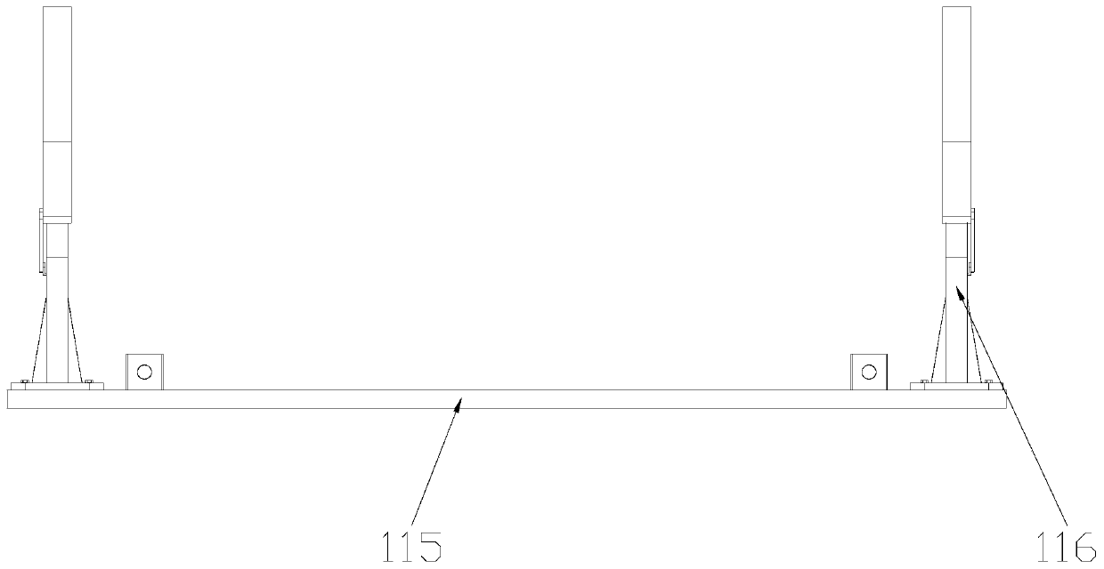
[0046] Such as figure 1 Shown is a schematic structural view of Embodiment 1 of the accompanying fixture for shaft products of the present invention. The accompanying clamp for shaft products in this embodiment includes a traveling base 115; at least two clamp units 116 whose axes are on the same straight line and are used to hold shaft products tightly are arranged at intervals on the accompanying base 115.

[0047]The clamp unit of this embodiment includes a holding base 101, and the two ends of the holding base 101 are respectively provided with a holding arm 102 that rotates with it, and the holding base 101 is provided with a handle for driving the holding arm 102 to rotate and hold Shaft products or flexible drive mechanisms for loosening shaft products; the base 101 of the holding device and the grip arm 102 are respectively provided with arc-shaped grooves or V-shaped grooves that cooperate with shaft products. Specifically, the holding device base 101 and the holding...

Embodiment 2

[0055] This embodiment also proposes an accompanying fixture for shaft products, including an accompanying base 115 . At least three clamp units 116 for clamping shaft products are arranged at intervals on the accompanying base 115 .

[0056] Among all the clamp units 116, the two clamp units 116 located at both ends are end clamp units, and the clamp unit 116 located between the two end clamp units is an intermediate clamp unit. The axes of the two end clamp units are always on the same straight line; among all the intermediate clamp units, the axis of at least one intermediate clamp unit is not collinear with the axes of the two end clamp units.

[0057] Specifically, the clamp unit 116 can be installed on the accompanying base 115 in various ways, such as:

[0058] All clamp units 116 are fixedly installed on the accompanying base 115; or,

[0059] The accompanying base 115 is provided with a longitudinal slide rail parallel to the straight line, and among all the clamp u...


PUM


Abstract

The invention discloses a fixture unit. The fixture unit comprises a clamp base, wherein clamping arms forming rotary fit with the clamp base are arranged at the two ends of the clamp base separately,and a flexible drive mechanism used for driving the clamping arms to rotate and clamp the shaft products or release the shaft products is arranged on the clamp base; and arc-shaped grooves or V-shaped grooves matched with the shaft products are formed in the clamp base and the clamping arms separately. The invention further discloses a follower fixture for the shaft products. The follower fixturefor the shaft products, and the fixture unit thereof are capable of realizing circumferential clamping fixing for the shaft products, being used for transferring the shaft products among different stations, and increasing the efficiency and accuracy.

Description

technical field [0001] The invention belongs to the technical field of mechanical tooling fixtures, in particular to an accompanying fixture for shaft products and a fixture unit thereof, in particular to an accompanying fixture suitable for large-scale shaft products. Background technique [0002] The accompanying fixture is a machine tool fixture that is automatically moved between each station with the installed workpiece. Accompanying fixtures are mainly used in automatic production lines, machining centers, flexible manufacturing systems, etc., for workpieces with irregular shapes that are not convenient for automatic positioning, clamping and transportation. After the workpiece is installed and positioned on the pallet, the pallet is transported to each station by the conveying device. The accompanying fixture is generally positioned on the machine tool with its bottom plane and two positioning holes, and is clamped by the clamping mechanism of the machine tool table ...

Claims


Application Information

Patent Timeline
Patent Type & Authority Patents(China)
IPC IPC(8): B23Q3/06B23Q7/00
CPCB23Q3/064B23Q7/00
Inventor 杨波陈嵘华王时龙陈俊明王彦凯杨叶枫
Owner CHONGQING UNIV
Features
  • R&D
  • Intellectual Property
  • Life Sciences
  • Materials
  • Tech Scout
  • Unparalleled Data Quality
  • Higher Quality Content
  • 60% Fewer Hallucinations
Learn More