Intelligent detection equipment of inching switch
A technology of intelligent detection and jog switch, applied in circuit breaker testing and other directions, can solve the problems of cumbersome troubleshooting process, inconvenient data recording, short wiring process, etc., to achieve easy troubleshooting, easy data recording, and short wiring process. Effect
- Summary
- Abstract
- Description
- Claims
- Application Information
AI Technical Summary
Problems solved by technology
Method used
Image

Examples
Example Embodiment
[0022] Example 1
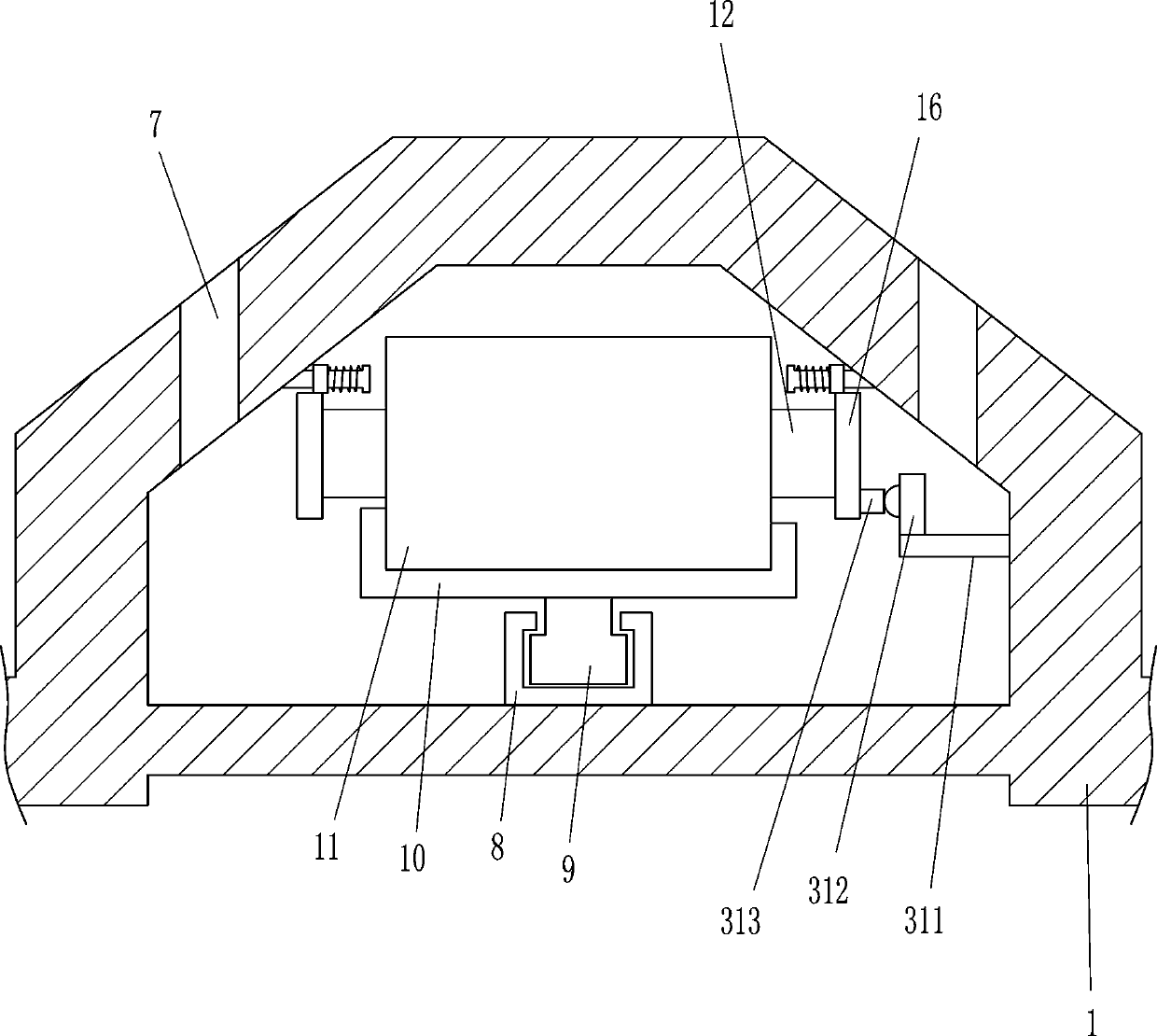
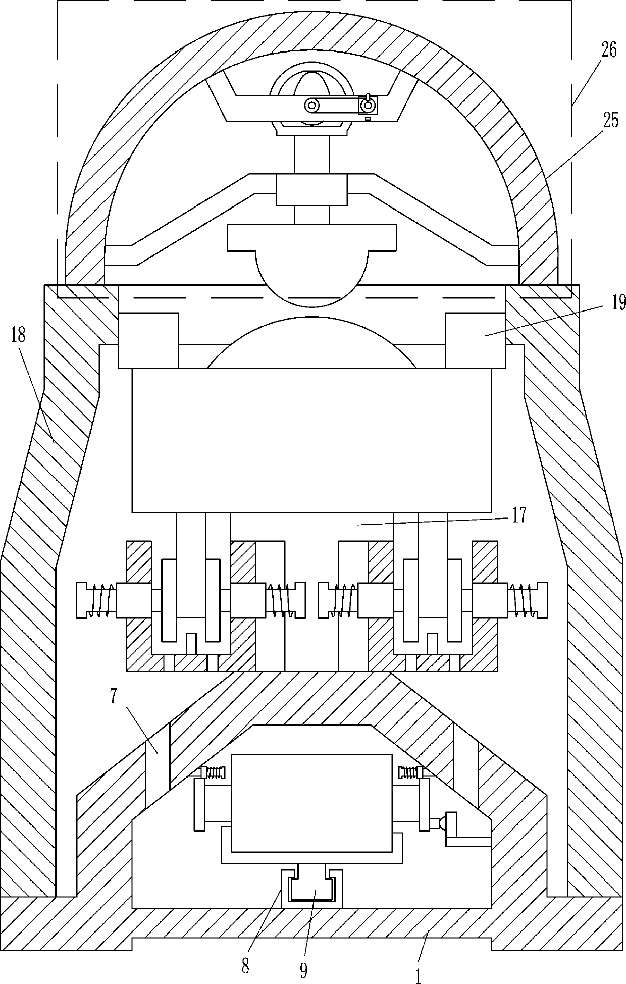
[0023] A kind of inching switch intelligent detection equipment, such as Figure 1-9 As shown, it includes a base frame 1, a first shaft sleeve 3, a first rotating shaft 4, a first rotating block 5, a first cover 6, a sliding rail 8, a sliding block 9, a placing plate 10, a battery box 11, and a contact block 12. The first guide rail 13, the first guide sleeve 14, the first spring 15, the contact piece 16, the T-shaped plate 17, the mounting box 18, the fixed block 19, the second sleeve 21, the second rotating shaft 22, the second rotating block 23. The second cover 24, the top box 25, the vibration device 26, the control box 27 and the main power switch 28, the top of the bottom frame 1 is provided with a mounting box 18, and the bottom frame 1 is connected to the mounting box 18 by welding, and the installation The lower part of the front side of the box 18 is provided with a first operating hole 2, and the upper part of the front side of the mounting box 18...
Example Embodiment
[0024] Example 2
[0025] A kind of inching switch intelligent detection equipment, such as Figure 1-9 As shown, it includes a base frame 1, a first shaft sleeve 3, a first rotating shaft 4, a first rotating block 5, a first cover 6, a sliding rail 8, a sliding block 9, a placing plate 10, a battery box 11, and a contact block 12. The first guide rail 13, the first guide sleeve 14, the first spring 15, the contact piece 16, the T-shaped plate 17, the mounting box 18, the fixed block 19, the second sleeve 21, the second rotating shaft 22, the second rotating block 23. The second cover 24, the top box 25, the vibration device 26, the control box 27 and the main power switch 28, the top of the bottom frame 1 is provided with a mounting box 18, and the lower part of the front side of the mounting box 18 is provided with a first operating hole 2 for installation The upper part of the front side of the box 18 is provided with a second operating hole 20. The lower left part of the fro...
Example Embodiment
[0027] Example 3
[0028] A kind of inching switch intelligent detection equipment, such as Figure 1-9 As shown, it includes a base frame 1, a first shaft sleeve 3, a first rotating shaft 4, a first rotating block 5, a first cover 6, a sliding rail 8, a sliding block 9, a placing plate 10, a battery box 11, and a contact block 12. The first guide rail 13, the first guide sleeve 14, the first spring 15, the contact piece 16, the T-shaped plate 17, the mounting box 18, the fixed block 19, the second sleeve 21, the second rotating shaft 22, the second rotating block 23. The second cover 24, the top box 25, the vibration device 26, the control box 27 and the main power switch 28, the top of the bottom frame 1 is provided with a mounting box 18, and the lower part of the front side of the mounting box 18 is provided with a first operating hole 2 for installation The upper part of the front side of the box 18 is provided with a second operating hole 20. The lower left part of the fro...
PUM
 Abstract
Description
Claims
Application Information
 - R&D Engineer
- R&D Manager
- IP Professional
- Industry Leading Data Capabilities
- Powerful AI technology
- Patent DNA Extraction
Browse by: Latest US Patents, China's latest patents, Technical Efficacy Thesaurus, Application Domain, Technology Topic.
© 2024 PatSnap. All rights reserved.Legal|Privacy policy|Modern Slavery Act Transparency Statement|Sitemap