Ultrasonic tester capable of realizing multilevel early warning and cooling

A technology of ultrasonic wave and tester, which is applied in the field of testing, can solve problems such as inaccurate measurement results, unfavorable user adjustments, and inability to realize multi-pole early warning, etc., to achieve the effects of avoiding danger, improving measurement accuracy, and accurate processing

Inactive Publication Date: 2019-11-05
孙毅
View PDF0 Cites 2 Cited by
  • Summary
  • Abstract
  • Description
  • Claims
  • Application Information

AI Technical Summary

Problems solved by technology

Since ultrasonic waves belong to the range of sound waves, their wave velocity C is related to temperature. The higher the temperature, the higher the wave velocity. If the temperature is not controlled, the final measurement results w

Method used


Image

  • Ultrasonic tester capable of realizing multilevel early warning and cooling

Examples


Example Embodiment

[0017] Example 1:

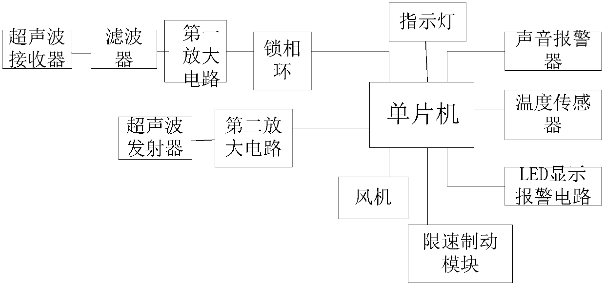
[0018] Such as figure 1 As shown, the present invention includes an ultrasonic tester capable of realizing multi-pole warning and cooling, including a single-chip microcomputer. The single-chip microcomputer is simultaneously connected with a sound alarm, a temperature sensor, an LED display alarm circuit, a fan, and a speed limit brake for limiting vehicle speed. Module, phase-locked loop and amplifying circuit. The first amplifying circuit is also connected to the phase-locked loop. A filter is also set between the first amplifying circuit and the ultrasonic receiver. The second amplifying circuit is also connected to the single chip microcomputer. An ultrasonic transmitter is also connected to the amplifier circuit; an indicator light is also connected to the single-chip microcomputer. The indicator light includes three color indicators of red, yellow and green. When the distance to the obstacle measured by the single-chip microcomputer is greater than 2m, ...

Example Embodiment

[0020] Example 2:

[0021] This embodiment is preferably as follows on the basis of Embodiment 1: When the red light and the yellow light are on, they will blink and rotate continuously. Since the light may not be clear during the day, but now not only the light is turned on, but also the light is flashing and bright, and at the same time, it is constantly rotating, reminding the user from multiple angles and multiple ways to make it take action in time , To avoid danger.

[0022] The first amplifier circuit is a differential amplifier circuit. The differential amplifier circuit utilizes the symmetry and negative feedback of the circuit parameters to effectively stabilize the static operating point. Under the condition of the circuit symmetry, the differential amplifier has a strong ability to suppress zero drift and suppress noise and interference.

[0023] The single-chip microcomputer adopts the model AT89C51. AT89C51 provides the following standard functions: 4k bytes of FLASH...


PUM


Abstract

The invention discloses an ultrasonic tester capable of realizing multilevel early warning and cooling, comprising a single chip microcomputer, wherein an audible alarm, a temperature sensor, an LED display alarm circuit, a draught fan, a speed limiting and braking module for limiting the vehicle speed, a phase-locked loop and an amplification circuit are connected to the single chip microcomputerat the same time, a first amplification circuit is further connected to the phase-locked loop, a filter is further disposed between the first amplification circuit and an ultrasonic receiver, a second amplification circuit is further connected to the single chip microcomputer, and an ultrasonic transmitter is further connected to the second amplification circuit; indicator lights are further connected to the single chip microcomputer, the indicator lights comprises indicator lights of three colors, that is, red, yellow and green, when the distance to an obstacle detected by the single chip microcomputer is greater than 2m, the green light is turned on; and when the distance to the obstacle is within 1-2m, the yellow light is turned on. Through the above structure, the ultrasonic tester disclosed by the invention can realize multilevel early warning, can better avoid the danger of collision with the obstacle, can also perform cooling via the draught fan, and has high measurement precision.

Description

technical field [0001] The invention relates to the testing field, in particular to an ultrasonic tester capable of realizing multi-pole early warning and cooling. Background technique [0002] In the field of ultrasonic measurement, there are four factors that limit the accuracy of ultrasonic measurement: the amplitude of the ultrasonic wave, the texture of the reflection, the angle between the reflected and incident waves, and the sensitivity of the receiving transducer. The ability of the receiving transducer to receive the sound pulse directly will determine the minimum measurable distance. In order to increase the coverage of the measurement and reduce the measurement error, multiple ultrasonic transducers can be used as a design method for multi-channel ultrasonic transmission or reception. Since ultrasonic waves belong to the range of sound waves, their wave speed C is related to temperature. The higher the temperature, the higher the wave speed. If the temperature i...

Claims


Application Information

Patent Timeline
IPC IPC(8): G01S15/93
CPCG01S15/931
Inventor 孙毅
Owner 孙毅
Why Eureka
Try Eureka