
Circulating liquid injection device and process for lithium battery

A liquid injection device, lithium battery technology, applied in battery pack parts, circuits, electrical components, etc., can solve problems such as explosion-proof valve bursting, low liquid injection efficiency, deformation, etc., to avoid vacuuming, achieve full infiltration, improve The effect of injection efficiency

Inactive Publication Date: 2019-11-05
湖北锂诺新能源科技有限公司
View PDF6 Cites 4 Cited by
  • Summary
  • Abstract
  • Description
  • Claims
  • Application Information

AI Technical Summary

Problems solved by technology

[0002] At present, most lithium-ion batteries are injected with electrolyte using the "high pressure and equal pressure" injection method. The main process flow of lithium-ion battery injection is now, vacuuming, liquid injection, pressurization, vacuum pressurization, standing, secondary Liquid injection and battery discharge. This method needs to vacuumize and break the vacuum inside and outside the lithium battery many times. It needs to accurately control the pressure inside and outside the battery. In addition, the internal pressure of the battery will be higher than the external pressure of the battery during the liquid injection process. Poor pressure control will lead to battery bulging, deformation, and explosion-proof valve bursting, etc., which will affect production efficiency and product quality; and this injection method has low injection efficiency and low absorption rate of electrolyte by the battery; in addition, the inside of the battery The metal dust and impurities cannot be discharged, which will affect the electrochemical performance of the battery

Method used


Image

  • Circulating liquid injection device and process for lithium battery
  • Circulating liquid injection device and process for lithium battery
  • Circulating liquid injection device and process for lithium battery

Examples


Embodiment Construction

[0030] In order to better understand the present invention, the invention will be described in detail below in conjunction with the accompanying drawings and specific examples.

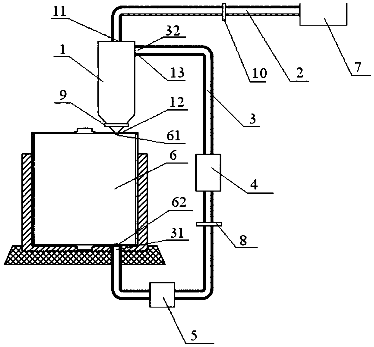
[0031] In order to solve the problem of low liquid injection efficiency in the existing lithium ion battery liquid injection process, the present invention provides a lithium battery circulation liquid injection device and a liquid injection process, through which the electrolyte circulates in the lithium battery to realize the electrolyte and the pole pieces Fully infiltrating, avoiding complex vacuuming and vacuum breaking procedures, and improving the efficiency of lithium battery injection. The preferred modes of the lithium battery circulation injection device and the injection process of the present invention will be described in detail below through specific examples.

[0032] See 2 and image 3 As shown, the present invention is improved on the basis of traditional lithium ion batteries, and ...


PUM


Abstract

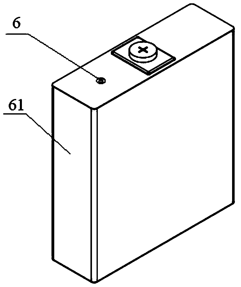
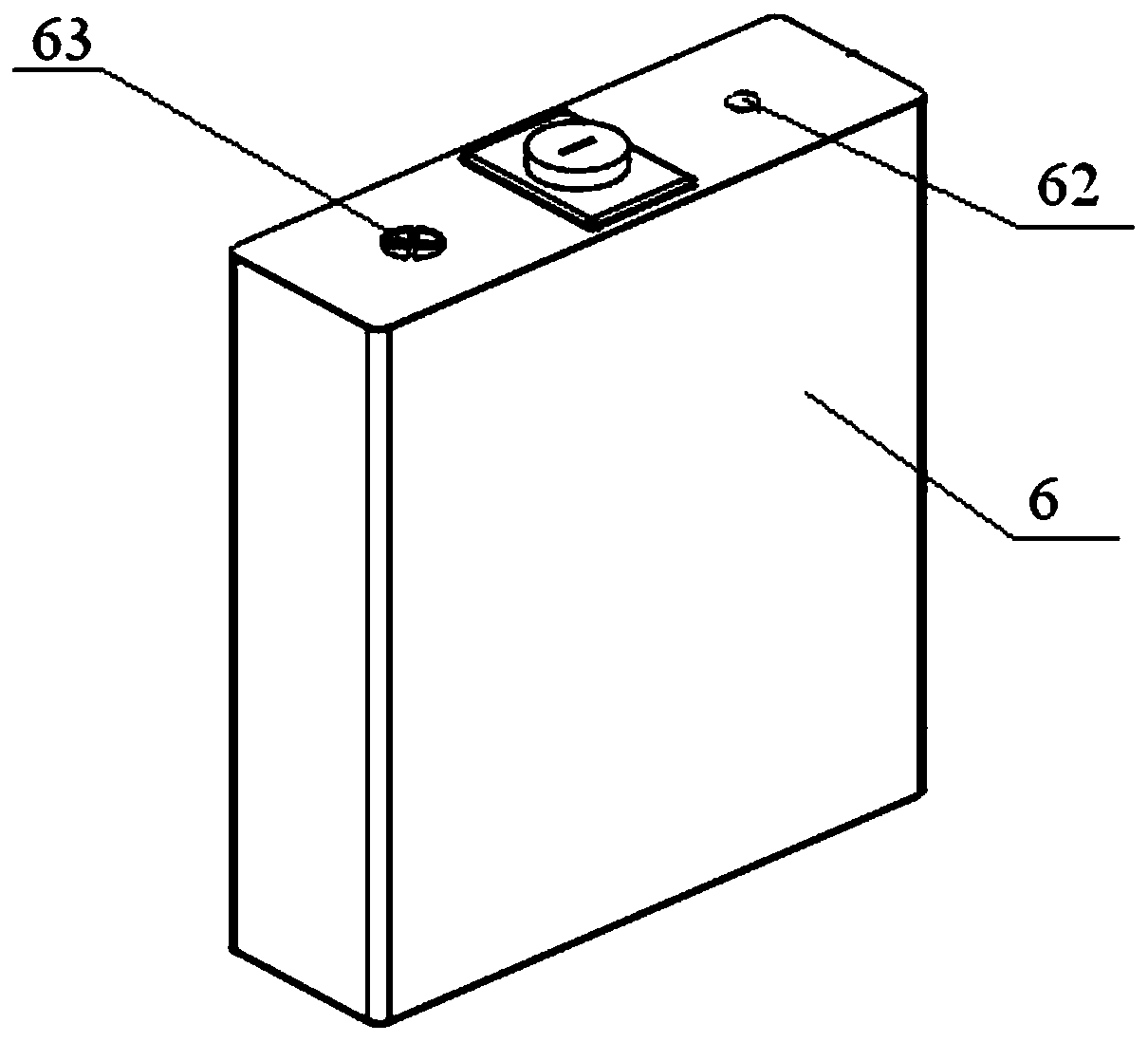
The invention relates to the field of lithium battery preparation, in particular to a circulating liquid injection device and process for a lithium battery. The circulating liquid injection device designed in the invention comprises a lithium battery with a liquid injection hole and a reflux inlet, an electrolyte storage tank, a liquid injection pipe, a liquid injection cup, a circulating pump anda circulating pipe, wherein the electrolyte storage tank, the electrolyte injection pipe, the electrolyte injection cup and the lithium battery are sequentially connected end to end to form an electrolyte injection passage; and the liquid injection cup, the lithium battery, the circulating pump and the circulating pipe are sequentially connected end to end in a closed-loop manner to form a closedelectrolyte circulating passage. Compared with an existing lithium battery liquid injection device, the electrolyte injection device comprises the electrolyte injection passage and the electrolyte circulating passage; the electrolyte is injected into the lithium battery through the electrolyte injection passage, and the electrolyte circulates in the lithium battery through the electrolyte circulating passage, so that the electrolyte and pole pieces are fully infiltrated, complex vacuumizing and vacuum breaking processes are avoided, and the liquid injection efficiency of the lithium battery is improved.

Description

technical field [0001] The invention relates to the field of lithium battery preparation, in particular to a lithium battery cycle liquid injection device and a liquid injection process. Background technique [0002] At present, most lithium-ion batteries are injected with electrolyte using the "high pressure and equal pressure" injection method. The main process flow of lithium-ion battery injection is now, vacuuming, liquid injection, pressurization, vacuum pressurization, standing, secondary Liquid injection and battery discharge. This method needs to vacuumize and break the vacuum inside and outside the lithium battery many times. It needs to accurately control the pressure inside and outside the battery. In addition, the internal pressure of the battery will be higher than the external pressure of the battery during the liquid injection process. Poor pressure control will lead to battery bulging, deformation, and explosion-proof valve bursting, etc., which will affect p...

Claims


Application Information

Patent Timeline
IPC IPC(8): H01M2/36
CPCH01M50/60H01M50/636Y02E60/10
Inventor 马卫陈刚张天赐陆玉明陈中华孙伟兵华诚杨梢王宇梁根兴江长清
Owner 湖北锂诺新能源科技有限公司
Learn More