Check patentability & draft patents in minutes with Patsnap Eureka AI!

A CRD method model test device

A model test device and CRD method technology, applied in teaching models, instruments, educational tools, etc., can solve the problem of being unable to quantitatively and accurately control the excavation speed and footage, unable to truly simulate the construction process of the CRD method, and unable to simultaneously study and support The deformation of the protective structure and the influence of different stiffnesses, etc., achieve the effect of convenient and fast adjustment

Active Publication Date: 2021-07-27
BEIJING JIAOTONG UNIV
View PDF5 Cites 0 Cited by
  • Summary
  • Abstract
  • Description
  • Claims
  • Application Information

AI Technical Summary

Problems solved by technology

[0004] In view of the above situation, in order to overcome the defects of the prior art, the present invention provides a CRD method model test device, which effectively solves the problem that the actual construction process of the CRD method cannot be truly simulated at present, and the excavation speed and footage cannot be quantitatively and accurately controlled. , and the problem that it is impossible to study the deformation and failure of the supporting structure and the influence of different stiffnesses at the same time

Method used


Image

  • A CRD method model test device
  • A CRD method model test device
  • A CRD method model test device

Examples


Embodiment 1

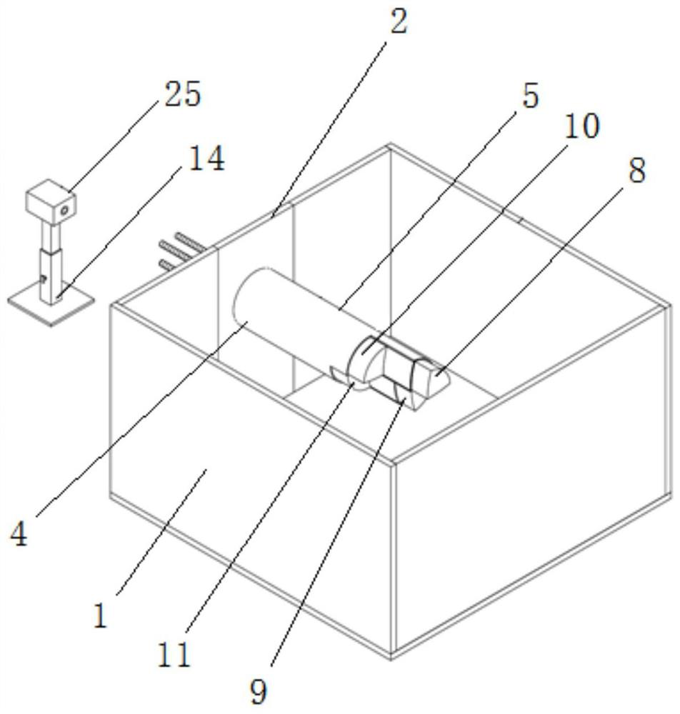
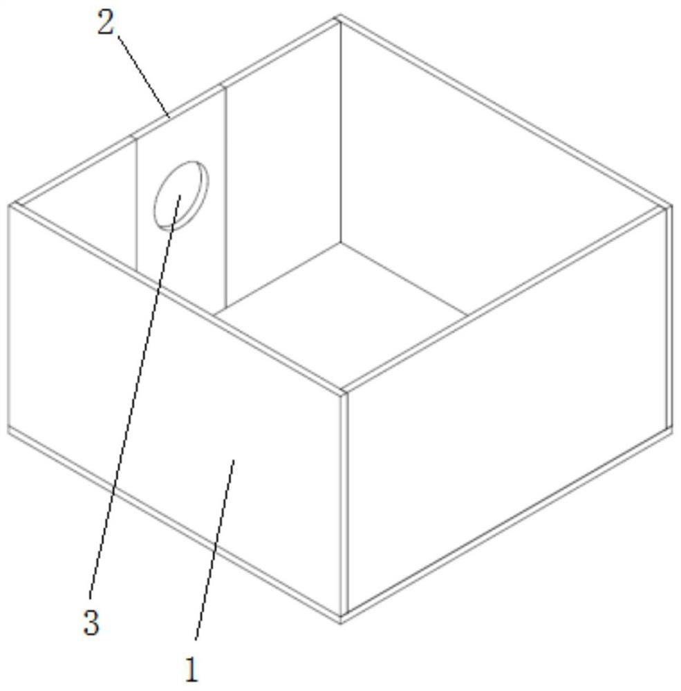
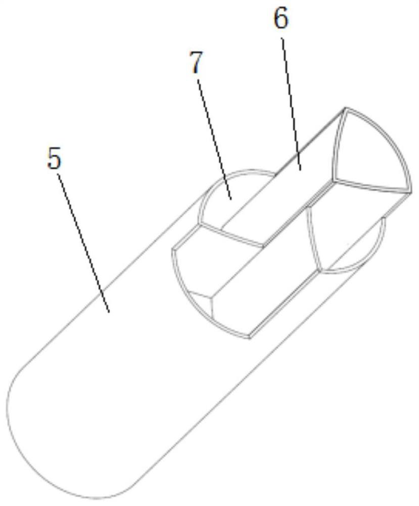
[0032] Embodiment one, by figure 1 , figure 2 , image 3 , Figure 4 , Figure 5 , Figure 6 , Figure 7 and Figure 8 It is given that the present invention includes a model box 1, which is convenient for filling surrounding rock materials for simulation tests. The middle part of one end of the model box 1 is movably connected with a glass plate 2, which is convenient for disassembly and cleaning of the inside of the model box 1. A connecting hole is opened in the middle of the glass plate 2 3. It is convenient to connect with the tunnel excavation mechanism 4. The tunnel excavation mechanism 4 is plugged inside the connection hole 3. The tunnel excavation mechanism 4 includes a support circular pipe 5, a cross middle partition 6, an excavation block groove 7, a first opening Excavation block 8, the second excavation block 9, the third excavation block 10, the fourth excavation block 11, threaded rod 12 and scale mark 13, the inside of the support circular pipe 5 right...

Embodiment 2

[0033] Embodiment 2. On the basis of Embodiment 1, the model box 1 is a box with an open top formed by bonding five pieces of toughened glass, and the middle part of the steel cover glass on the left side of the model box 1 is provided with a slot for matching with the glass plate 2 .

Embodiment 3

[0034] Embodiment 3, on the basis of Embodiment 2, the glass plate 2 and the two sides of the slot are fixedly connected by bolts, and the glass plate 2 is a detachable structure, and the glass plate 2 of the detachable structure is set so that the device can be used after use. Quick disassembly will clean up the internal surrounding rock materials.


PUM


Abstract

The invention relates to the technical field of CRD construction model test, and discloses a CRD method model test device, which solves the problem that the actual construction process of the CRD method cannot be truly simulated at present, the excavation speed and footage cannot be quantitatively and accurately controlled, and the simultaneous To study the deformation and damage of the support structure and the influence of different stiffnesses, it includes a model box, the middle part of one end of which is movably connected with a glass plate. length to simulate the length of the unsupported section, if the right end of each excavation block is flush with the right end of the supporting pipe, then simulate the situation of immediate support after tunnel excavation, through the longitudinal length of the four parts on the right side of the supporting pipe To simulate the longitudinal spacing of each excavation part, the actual construction process of the CRD method can be simulated; the excavation speed can be accurately controlled by selecting the same motor speed, and the excavation footage can be controlled by observing the scale marks on the threaded rod.

Description

technical field [0001] The invention belongs to the technical field of CRD construction model test, in particular to a CRD method model test device. Background technique [0002] With the rapid development of the transportation industry, my country has become a veritable tunnel country, and a series of tunnel construction methods suitable for different conditions have been formed. When the tunnel section is large, the CRD method is usually used for construction. The full name of the CRD method is the cross-middle partition method. It is a tunnel construction method suitable for weak surrounding rocks. During construction, the entire tunnel section is divided into four small sections, which is beneficial to control the deformation of the surrounding rock. [0003] Due to the complexity and uncertainty of tunnel engineering, it is inevitable that the surrounding rock and supporting structure will be deformed or even destroyed when the CRD method is used for construction. There...

Claims


Application Information

Patent Timeline
Patent Type & Authority Patents(China)
IPC IPC(8): G09B25/00
CPCG09B25/00
Inventor 房倩于霖张顶立徐曈曹利强刘道平苏洁
Owner BEIJING JIAOTONG UNIV
Features
  • R&D
  • Intellectual Property
  • Life Sciences
  • Materials
  • Tech Scout
  • Unparalleled Data Quality
  • Higher Quality Content
  • 60% Fewer Hallucinations
Learn More