Organic electroluminescent element and electronic device
An electroluminescent element, organic technology, applied in the direction of electrical components, organic semiconductor devices, luminescent materials, etc., can solve the problems of practical research in the ascendant
- Summary
- Abstract
- Description
- Claims
- Application Information
AI Technical Summary
Problems solved by technology
Method used
Image

Examples
Embodiment 1
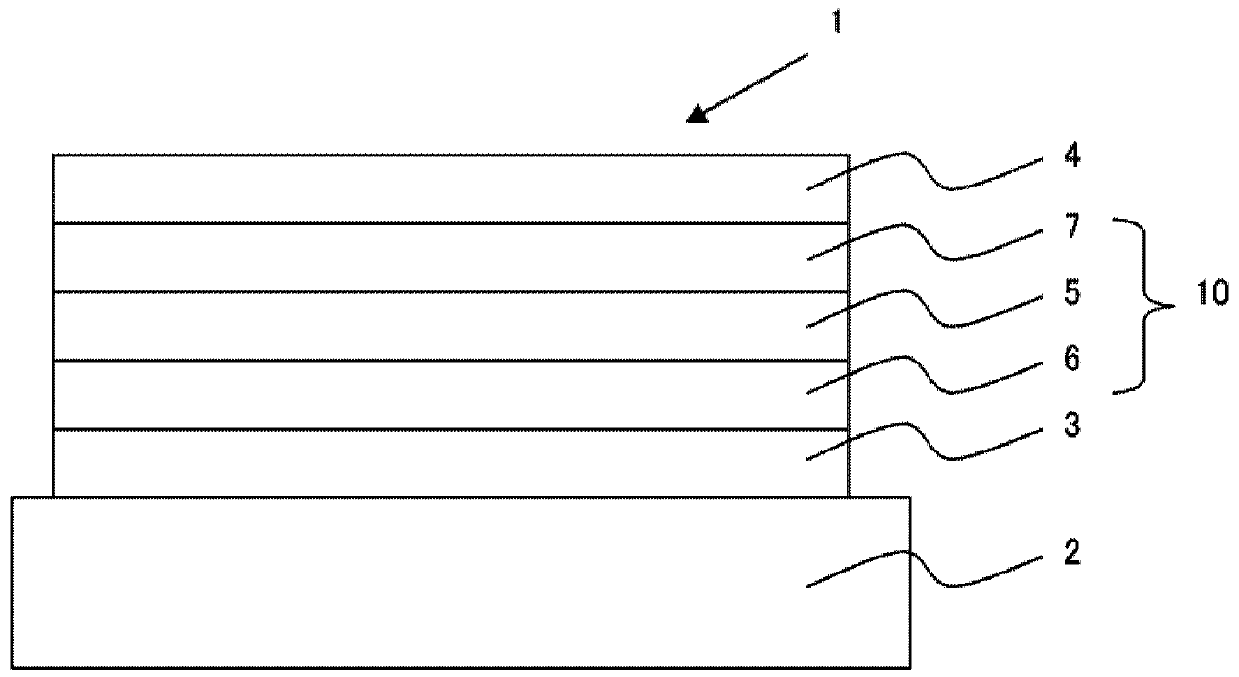
[0827] Fabrication of organic EL elements
[0828] A 25 mm x 75 mm x 1.1 mm glass substrate (manufactured by Geomatec) with an ITO transparent electrode (anode) was ultrasonically cleaned in isopropanol for 5 minutes, and then UV ozone cleaning was performed for 30 minutes. The film thickness of ITO was 130 nm.
[0829] The above-mentioned glass substrate after cleaning was installed on the substrate holder of the vacuum evaporation device, and the compound HI-1 was first evaporated on the side where the transparent electrode was formed to cover the transparent electrode to form a hole injection layer with a film thickness of 5 nm. .
[0830] Compound HT-1 was vapor-deposited on this hole injection layer to form a first hole transport layer with a film thickness of 80 nm.
[0831] Next, the compound HT-2 was vapor-deposited on the first hole transport layer to form a second hole transport layer with a film thickness of 10 nm.
[0832] Then, compound BH1-1 (first compound), ...
Embodiment 2~13 and comparative example 1~10
[0846] Each organic EL device containing the first compound shown in Table 1, the second compound, and the dopant material in the mass ratio shown in Table 1 was fabricated and evaluated in the same manner as in Example 1. The results are shown in Table 1.
[0847] Materials used in Examples 1 to 13 and Comparative Examples 1 to 10 are shown below.
[0848] Hole injection layer, hole transport layer material
[0849] [chem 156]
[0850]
[0851] electron transport layer material
[0852] [chem 157]
[0853]
[0854] Dopant material
[0855] [chem 158]
[0856]
[0857] first compound
[0858] [chem 159]
[0859]
[0860] second compound
[0861] [chem 160]
[0862]
[0863] [Table 1]
[0864]
[0865] Compared with the single-host organic EL elements comprising the first compound and the dopant material of Comparative Examples 1-10, the co-host organic components comprising the second compound in addition to the first compound and the dopant materia...
Embodiment 14~20 and comparative example 11~13
[0868] Each organic EL element containing the first compound shown in Table 1, the second compound, and the dopant material in the mass ratio shown in Table 2 was fabricated and evaluated in the same manner as in Example 1. The results are shown in Table 2.
[0869] Materials used in Examples 14 to 20 and Comparative Examples 11 to 13 are shown below.
[0870] Dopant material
[0871] [chem 161]
[0872]
[0873] second compound
[0874] [chem 162]
[0875]
[0876] [Table 2]
[0877]
[0878] Compared with the single-host organic EL elements comprising the first compound and the dopant material of Comparative Examples 11-13, the co-host organic components comprising the second compound in addition to the first compound and the dopant material of Examples 14-20 The EL element has a long life. That is, when comparing organic EL elements under the same conditions except for the presence or absence of the second compound, the EL element of the present invention has...
PUM
| Property | Measurement | Unit |
|---|---|---|
| thickness | aaaaa | aaaaa |
| thickness | aaaaa | aaaaa |
| thickness | aaaaa | aaaaa |
Abstract
Description
Claims
Application Information
 - R&D
- Intellectual Property
- Life Sciences
- Materials
- Tech Scout
- Unparalleled Data Quality
- Higher Quality Content
- 60% Fewer Hallucinations
Browse by: Latest US Patents, China's latest patents, Technical Efficacy Thesaurus, Application Domain, Technology Topic, Popular Technical Reports.
© 2025 PatSnap. All rights reserved.Legal|Privacy policy|Modern Slavery Act Transparency Statement|Sitemap|About US| Contact US: help@patsnap.com