Supercharge Your Innovation With Domain-Expert AI Agents!

Mechanical flying bird flying demonstration device

A demonstration device and technology for flying birds, applied in the field of science and education, can solve problems such as the inability to demonstrate the flying attitude of birds

Active Publication Date: 2019-11-29
安徽盛鸿展览工程有限公司
View PDF7 Cites 0 Cited by
  • Summary
  • Abstract
  • Description
  • Claims
  • Application Information

AI Technical Summary

Problems solved by technology

In order to make it easier for people to understand the flying state of birds, people use mechanical structures to build flying bird models. Existing mechanical flying birds cannot demonstrate the flying posture of birds

Method used


Image

  • Mechanical flying bird flying demonstration device
  • Mechanical flying bird flying demonstration device
  • Mechanical flying bird flying demonstration device

Examples


Embodiment 1

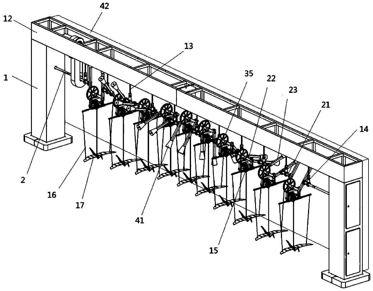
[0024] Such as figure 1 Shown; A kind of mechanical flying bird demonstration device, comprises:

[0025] There are two vertical beams 1, two vertical beams 1 are installed, the upper part of the two vertical beams 1 is provided with a crossbeam 12, the lower part of the crossbeam 12 is fixed with a pull rod 13, and the lower end of the pull rod 13 is equipped with a suspension axle seat 14;

[0026] Crankshaft 2, crankshaft 2 is installed on the suspension shaft seat 14, and the two ends of crankshaft 2 extend into the vertical beam 1 on both sides respectively, and the drive motor is installed inside the vertical beam 1, and the drive motor provides power for the crankshaft;

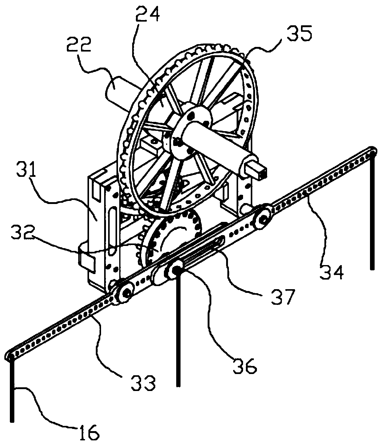
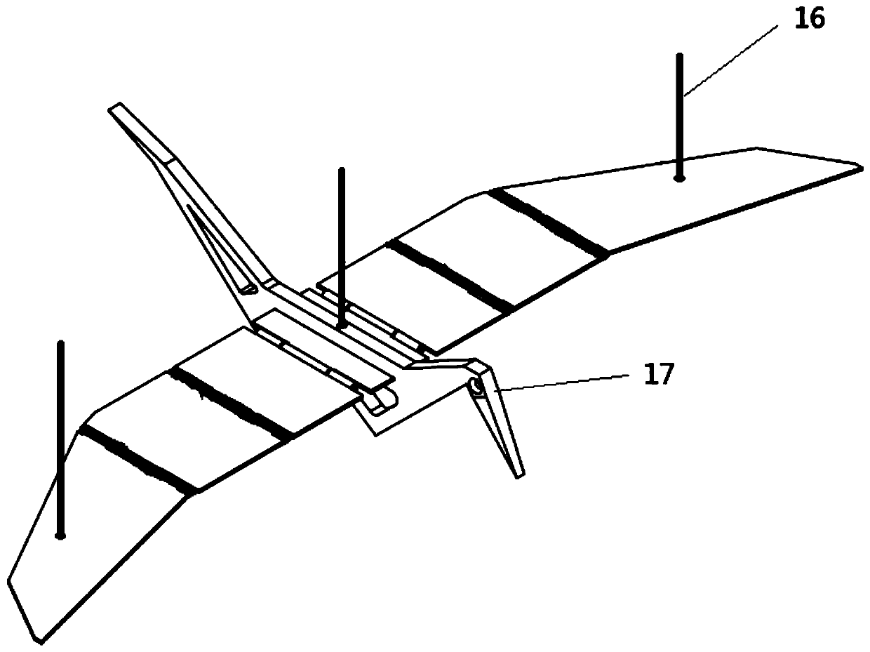
[0027] An action driving mechanism 15 is installed on the crankshaft 2, and the action driving mechanism 15 is connected with a traction rope 16, and the lower end of the traction rope 16 is connected with a flying bird 17.

[0028] A mechanical flying bird demonstration device, the working principle:...

Embodiment 2

[0031] Such as figure 1 Shown; A kind of mechanical flying bird demonstration device, comprises:

[0032] There are two vertical beams 1, two vertical beams 1 are installed, the upper part of the two vertical beams 1 is provided with a crossbeam 12, the lower part of the crossbeam 12 is fixed with a pull rod 13, and the lower end of the pull rod 13 is equipped with a suspension axle seat 14;

[0033] Crankshaft 2, crankshaft 2 is installed on the suspension shaft seat 14, and the two ends of crankshaft 2 extend into the vertical beam 1 on both sides respectively, and the drive motor is installed inside the vertical beam 1, and the drive motor provides power for the crankshaft;

[0034] An action driving mechanism 15 is installed on the crankshaft 2, and the action driving mechanism 15 is connected with a traction rope 16, and the lower end of the traction rope 16 is connected with a flying bird 17.

[0035] A mechanical flying bird demonstration device, the working principle:...


PUM


Abstract

The invention discloses a mechanical flying bird flying demonstration device, and relates to the field of science and education. The mechanical flying bird flying demonstration device comprises two vertical beams and a crankshaft, wherein a cross beam is erected on the upper parts of the two vertical beams; pulling rods are fixed at the lower part of the cross beam; a suspension shaft seat is mounted at the lower end of each corresponding pulling rod; the crankshaft is mounted on the suspension shaft seats; the two ends of the crankshaft extend into vertical beams at the two sides respectively; a driving motor is installed inside the corresponding vertical beam and provides power for the crankshaft; action driving mechanisms are installed on the crankshaft; and traction ropes are connectedto the corresponding action driving mechanisms, and the lower ends of the traction ropes are connected with corresponding flying birds. The traction ropes are suspended on the crankshaft, the flyingbirds are suspended by the corresponding traction ropes, and when the crankshaft rotates, the traction ropes are pulled to move up and down, so that the flying birds float up and down, and the flyingfloating postures of the flying birds can conveniently observed.

Description

technical field [0001] The invention relates to the field of science and education, in particular to a mechanical bird flight demonstration device. Background technique [0002] Mechanical structures are widely used in production and life. In order to meet the needs of laboratories and popular science museum exhibitions, so that learners and viewers can learn the movement and application of machinery, it is necessary to study some specific mechanical models. [0003] Birds stand on the ground and flap their wings downward in the same direction as the earth's gravitational force. Due to inertia, the air in the lower part of the wings will not immediately follow the downward movement of the wings, so the air pressure in the lower parts of the wings will rise. Also due to inertia, the air in the upper part of the wings The air will not follow the wings down immediately, so the air pressure on the upper part of the wings will be reduced, so that there is a pressure difference be...

Claims


Application Information

Patent Timeline
Patent Type & Authority Applications(China)
IPC IPC(8): G09B25/00
CPCG09B25/00
Inventor 李立新郑杨浩朱高吴春生王业能
Owner 安徽盛鸿展览工程有限公司
Features
  • R&D
  • Intellectual Property
  • Life Sciences
  • Materials
  • Tech Scout
  • Unparalleled Data Quality
  • Higher Quality Content
  • 60% Fewer Hallucinations
Learn More