Supercharge Your Innovation With Domain-Expert AI Agents!

Rail bridge beam end jacking and repairing device

A technology for overhauling equipment and railways, which is applied in bridge maintenance, bridges, bridge construction, etc., and can solve problems such as unfavorable force on the track, large area of ​​concrete crushing, and longitudinal movement of the beam body.

Active Publication Date: 2021-06-01
SHIJIAZHUANG TIEDAO UNIV
View PDF0 Cites 0 Cited by
  • Summary
  • Abstract
  • Description
  • Claims
  • Application Information

AI Technical Summary

Problems solved by technology

[0003]There are many reasons for the tightness of the beam end. Most of the bridges on soft soil foundation are caused by the instability of the foundation and the inclination of the abutment, which in turn causes the abutment to move forward or measure the inclination. In cold and rainy areas, frost heave often causes abutments to lean forward or tilt, and damage to supports can also cause longitudinal movement of beams, which in turn leads to tightness of adjacent bridge spans.
The number of beam end jacking diseases is relatively small, but once this kind of disease occurs, it will cause damage to the bridge expansion device and loss of function. endanger driving safety
At present, there are few studies on beam end jacking defects, and the inspection of the defects is mostly carried out by hanging balls or measurement methods. There is no reasonable and efficient beam end jacking daily inspection and long-term monitoring devices and methods, and it is difficult to accurately grasp the beam end. Keep track of the degree and development trend of the disease, and cannot achieve real-time remediation

Method used


Image

  • Rail bridge beam end jacking and repairing device
  • Rail bridge beam end jacking and repairing device
  • Rail bridge beam end jacking and repairing device

Examples


Embodiment 1

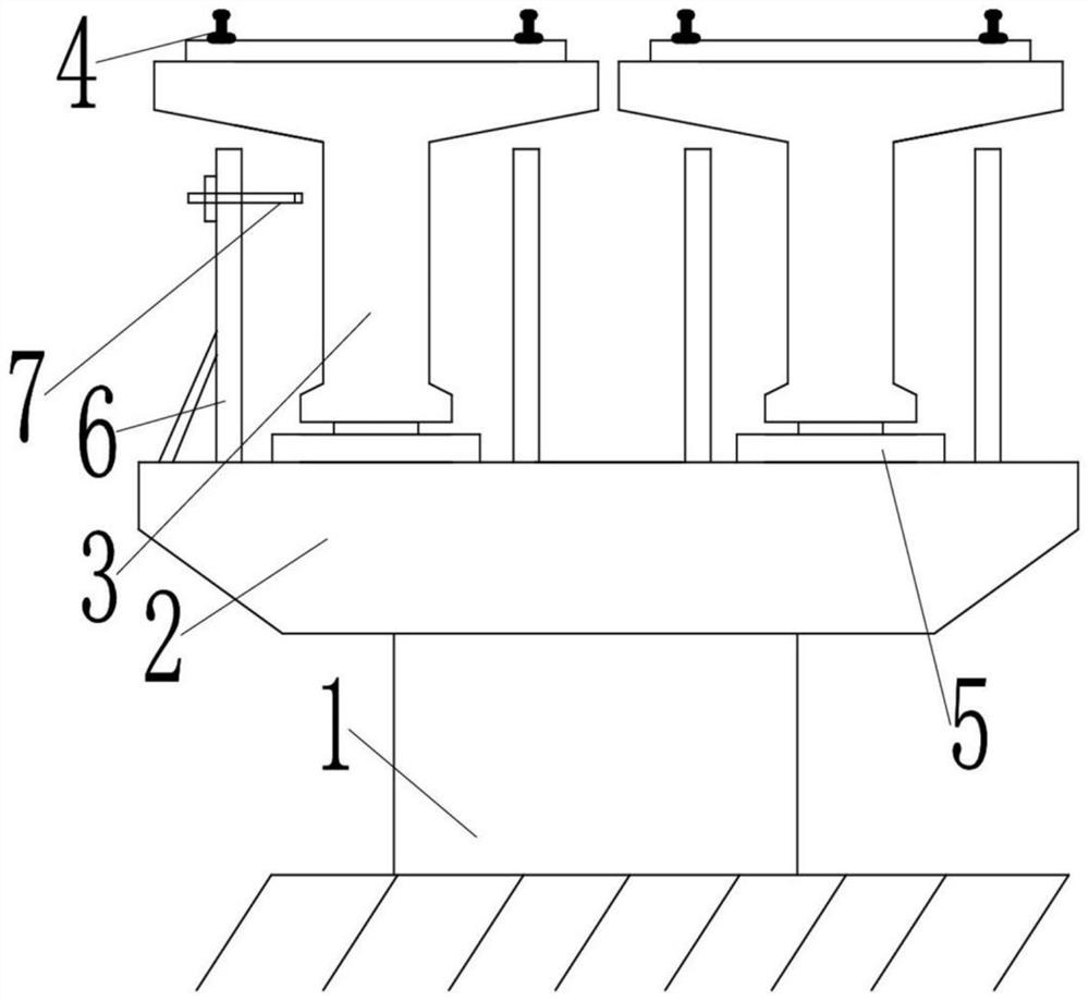
[0025] In the first embodiment, the displacement detection device 8 includes a combined support channel steel structure 6 set on the cover beam 2, and a slideway type displacement sensor 7 set on the combined support channel steel structure 6. The disadvantage is that real-time accurate detection cannot be realized, and the cost High, manual coordination is required, the structure is complex, and it is not suitable for mass use.

Embodiment 2

[0026] In the second embodiment, the displacement detection device 8 includes a cylinder tailstock arranged at the head end of a T-beam 3 and positioned at the upper and lower sides of the vertical beam of the T-beam 3, a displacement piston member 17 arranged in the cylinder tailstock for longitudinal movement, and a The return spring 18 on the displacement piston 17, the outer top fitting 19 that is arranged at the tail end of a T beam 3 and is used to correspond to the head of the displacement piston 17, and the triangle between the back of the outer top fitting 19 and the T beam 3 Rib 20;

[0027] The center-to-center distance of the cylinder tailstock is greater than or equal to the width of the T-beam 3 crossbeam.

[0028] Since the T-beam is solid, when the side moves or deflects or approaches, the edges of both ends approach first or at the same time. As long as the two ends are monitored, pre-judgment detection can be realized and the disadvantages of post-processing ...


PUM


Abstract

The invention relates to a device and method for jacking up and overhauling the beam end of a railway bridge, which includes a displacement detection device arranged between adjacent T beams, anti-subsidence devices arranged on both sides of the T beam, and a remedial device for walking on the track; The anti-subsidence device includes anti-subsidence accessories linearly installed on both sides of the vertical beam, guide rails arranged on the T-beam, anti-collision elastic seats arranged at both ends of the guide rail, mobile hangers arranged on both ends of the guide rail, setting The side guide wheels and the bottom guide wheels which are respectively in contact with the guide track on the mobile suspension base, the suspension legs arranged at both ends of the mobile suspension base, and the suspension ropes connected between the suspension base and the anti-subsidence fittings. The invention has reasonable design, compact structure and convenient use.

Description

technical field [0001] The invention relates to a device and method for checking and repairing the beam end of a railway bridge. The invention relates to the field of inspection / detection and evaluation of the technical condition of a heavy-duty railway bridge, in particular to a device and method for measuring the beam end of a railway bridge. Routine inspection and real-time monitoring of longitudinal displacement and vertical displacement of beam ends and abutments. Background technique [0002] At present, "heavy freight freight" is another development focus of my country's railways after "passenger high speed". Due to impact and fatigue, bridge diseases appear in large numbers and develop rapidly. The beam end jacking disease is a relatively common disease in heavy-haul railways, which is specifically manifested as the gap between the adjacent span beam end or the beam end and the abutment is too small or tight, and in severe cases, the beam or abutment concrete collaps...

Claims


Application Information

Patent Timeline
Patent Type & Authority Patents(China)
IPC IPC(8): E01D22/00G01B21/02G01B7/16
CPCE01D22/00
Inventor 陈树礼郭睿白世辉郎鹏飞李超冯小利许宏伟刘永前
Owner SHIJIAZHUANG TIEDAO UNIV
Features
  • R&D
  • Intellectual Property
  • Life Sciences
  • Materials
  • Tech Scout
  • Unparalleled Data Quality
  • Higher Quality Content
  • 60% Fewer Hallucinations
Learn More