Supercharge Your Innovation With Domain-Expert AI Agents!

A feeding device for an automated machine tool

A technology of feeding device and machine tool, which is applied in the attachment device of shearing machine, shearing device, metal processing equipment, etc., can solve the problems of low safety, hidden safety hazards, and narrow application range, and achieve the improvement of bar quality and cutting length. Adjustable, Wide Range of Effects

Inactive Publication Date: 2020-11-27
ZHENGZHOU TECHN COLLEGE
View PDF12 Cites 0 Cited by
  • Summary
  • Abstract
  • Description
  • Claims
  • Application Information

AI Technical Summary

Problems solved by technology

[0002] In the process of processing bars by machine tools, long bars need to be cut into short bars of a specified length. During the cutting process, long bars need to be transported continuously. The existing feeding method is manual feeding. Low efficiency, high labor intensity, and there are certain safety hazards in manual feeding. During the feeding process, long bars are prone to side roll, low safety, cutting length cannot be adjusted, narrow application range, and slag and dust appear during the cutting process. The phenomenon of random flying of impurities, poor cutting environment, and cannot meet the processing requirements. Therefore, it is urgent to design a cutting machine with high feeding efficiency, low labor intensity, high safety, good clamping effect, no damage to materials, high cutting accuracy, and long cutting length. Adjustable, wide application range, good impurity removal effect, no damage to the cutting environment, and automatic machine tool feeding device that meets processing requirements

Method used


Image

  • A feeding device for an automated machine tool
  • A feeding device for an automated machine tool
  • A feeding device for an automated machine tool

Examples


Embodiment 1

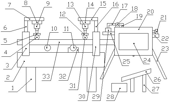
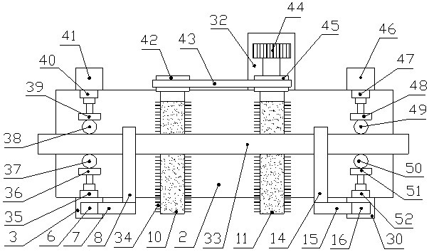
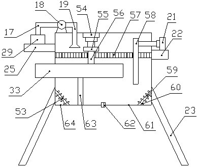
[0018] Such as Figure 1-3As shown, a feeding device for an automated machine tool, which includes a frame 2, a bar 33 and a cutting box 20, the lower end of the frame 2 is equipped with a leg A1, and the left and right sides of the front end of the frame 2 are The sides are respectively fixedly connected with mounting plate A3 and mounting plate C30, and the rear end of the frame 2 is fixedly connected with mounting plate B41, mounting plate E32 and mounting plate D46 in sequence from left to right, and the described mounting plate A3 and mounting plate The middle part of the rear end of C30 is equipped with hydraulic cylinder A35 and hydraulic cylinder C52 respectively, and the free ends of the piston rods of described hydraulic cylinder A35 and hydraulic cylinder C52 are connected with clamping block A36 and clamping block C51 respectively, and the clamping block A36 and clamping block C51 are respectively connected. The other ends of the block A36 and the clamping block C5...

Embodiment 2

[0021] Such as Figure 1-3 As shown, a feeding device for an automated machine tool, which includes a frame 2, a bar 33 and a cutting box 20, the lower end of the frame 2 is equipped with a leg A1, and the left and right sides of the front end of the frame 2 are The sides are respectively fixedly connected with mounting plate A3 and mounting plate C30, and the rear end of the frame 2 is fixedly connected with mounting plate B41, mounting plate E32 and mounting plate D46 in sequence from left to right, and the described mounting plate A3 and mounting plate The middle part of the rear end of C30 is equipped with hydraulic cylinder A35 and hydraulic cylinder C52 respectively, and the free ends of the piston rods of described hydraulic cylinder A35 and hydraulic cylinder C52 are connected with clamping block A36 and clamping block C51 respectively, and the clamping block A36 and clamping block C51 are respectively connected. The other ends of the block A36 and the clamping block C...


PUM


Abstract

The invention discloses a feeding device of an automatic machine tool. The feeding device comprises a machine frame, a bar material and a material cutting box, wherein one end of a clamping block A and one end of a clamping block C are respectively provided with a clamping wheel A and a clamping wheel C, one end of a clamping block B and one end of a clamping block D are respectively provided witha clamping wheel B and a clamping wheel D, the lower ends of a pressing block A and a pressing block B are respectively provided with a pressing wheel A and a pressing wheel B, an output shaft of themotor is connected with a driving wheel, the front end of the driving wheel and the front end of a driven wheel connected with the driving wheel are respectively connected with a driving shaft and adriven shaft, the bar material is placed on the driving shaft and the driven shaft, the free end of a piston rod of a hydraulic cylinder G is connected with a limiting plate, the lower end of a fixingblock is connected with an upper cutter, the lower ends of the inner walls of the left side and the right side of the material cutting box are respectively hinged with a baffle A and a baffle B, a discharging plate is arranged below the material cutting box, and a material collecting box is arranged below the left end of the discharging plate. The feeding device has the advantages of high feedingefficiency, high safety, good clamping effect, no damage to materials, high cutting precision, adjustable cutting length and good impurity removal effect.

Description

technical field [0001] The invention relates to the technical field of machine tool processing, in particular to a feeding device for an automatic machine tool. Background technique [0002] In the process of processing bars by machine tools, long bars need to be cut into short bars of a specified length. During the cutting process, long bars need to be transported continuously. The existing feeding method is manual feeding. Low efficiency, high labor intensity, and there are certain safety hazards in manual feeding. During the feeding process, long bars are prone to side roll, low safety, cutting length cannot be adjusted, narrow application range, and slag and dust appear during the cutting process. The phenomenon of random flying of impurities, poor cutting environment, and cannot meet the processing requirements. Therefore, it is urgent to design a cutting machine with high feeding efficiency, low labor intensity, high safety, good clamping effect, no damage to materials...

Claims


Application Information

Patent Timeline
Patent Type & Authority Patents(China)
IPC IPC(8): B23D33/02
CPCB23D33/02
Inventor 屈晓莉王雪赵娟萍马鑫张延萍陶琬丛
Owner ZHENGZHOU TECHN COLLEGE
Features
  • R&D
  • Intellectual Property
  • Life Sciences
  • Materials
  • Tech Scout
  • Unparalleled Data Quality
  • Higher Quality Content
  • 60% Fewer Hallucinations
Learn More