Unlock instant, AI-driven research and patent intelligence for your innovation.

concrete pouring device

A concrete and positioning ring technology, applied in the direction of molds, etc., can solve problems such as easy shaking and offset, poor bearing capacity of concrete columns, lack of fixation of inner cylinders, etc.

Active Publication Date: 2020-12-08
ZHENGZHOU INST OF TECH
View PDF5 Cites 0 Cited by
  • Summary
  • Abstract
  • Description
  • Claims
  • Application Information

AI Technical Summary

Problems solved by technology

[0007] In view of the above situation, in order to overcome the defects of the prior art, the present invention provides a concrete pouring device, which effectively solves the problems of lack of fixation of the existing inner cylinder, easy sloshing and offset, and poor bearing capacity of plain concrete columns.

Method used


Image

  • concrete pouring device
  • concrete pouring device
  • concrete pouring device

Examples


Embodiment 1

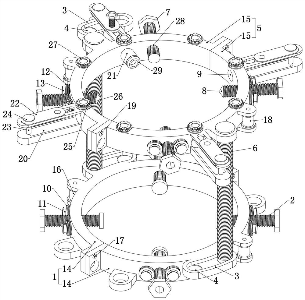
[0038] Embodiment 1, the present invention is a concrete pouring device, which is characterized in that it includes an outer skin placed on the ground, an inner cylinder is placed coaxially inside the outer skin, and concrete is poured between the outer skin and the inner cylinder. Place the formwork, brush oil on the formwork, then place the outer skin and inner cylinder on the formwork and pour;

[0039] It also includes a base ring 1 that is detachably connected to the ground and is sleeved outside the outer skin. When there is a template, it is detachably connected to the template. The uniform thread engagement of the base ring 1 through the base ring 1 is The four basic screws 2 realize synchronous feeding through the transmission structure of the basic ring 1 fixedly connected to the side wall of the basic ring 1, that is, one of the four basic screws 2 is rotated, and the four basic screws are driven by the transmission structure of the basic ring 1. Two basic screw rod...

Embodiment 2

[0041] Embodiment 2. On the basis of Embodiment 1, this embodiment provides a specific transmission structure of the basic ring 1 and the transmission structure of the positioning ring 5. Specifically, refer to image 3 , the transmission structure of the basic ring 1 includes the basic driven screw 10 that is respectively connected to the two sides of the four basic screws 2, and the eight basic driven screws 10 are all coaxially fixedly connected with the basic wire pulley 11, and the different basic screw rods 2 The two adjacent basic wire wheels 11 are connected by ropes, that is, one basic screw rod 2 is rotated to drive the basic driven screw rods 10 on both sides to rotate, and the adjacent basic driven screw rods are driven by the basic wire wheel 11 and the rope. 10 rotates, thereby driving the adjacent basic screw rod 2 to rotate, thereby realizing the synchronous rotation of the four basic screw rods 2, in order to facilitate better positioning of the outer skin, the...

Embodiment 3

[0044] Embodiment 3, on the basis of Embodiment 1 or 2, the basic ring 1 is composed of two detachably connected basic half rings 14, and the described positioning ring 5 is composed of two detachably connected positioning half rings 15 Composition, the basic ring 1 and the positioning ring 5 are set to be composed of two corresponding half rings, which is convenient for the disassembly and installation of the basic ring 1 and the positioning ring 5, and the two ends of each positioning ring 5 and the basic ring 1 are fixedly connected with The fixing plate and the fixing plate are provided with threaded holes, which are convenient for users to fix by bolts.


PUM


Abstract

The invention relates to a concrete pouring device. The device effectively solves the problems that an existing inner cylinder lacks fixation, so that shaking and offset are prone to be caused, and aplain concrete column is poor in bearing capacity. According to the technical scheme for solving the problems, the device comprises an outer skin placed on the ground, wherein an inner cylinder is coaxially placed in the outer skin; and the device further comprises a foundation ring which is detachably connected to the ground and is arranged outside the outer skin in a sleeving mode, wherein fourfoundation screw rods penetrating through the foundation ring are uniformly in threaded engagement with the periphery of the foundation ring, the four foundation screw rods realize synchronous feedingthrough a foundation ring transmission structure fixedly connected to the side wall of the foundation ring, two foundation grooves are uniformly and fixedly connected to the side wall of the foundation ring, and the two ends of the two foundation grooves are provided with circular positioning grooves with the depths larger than those of other parts of the foundation grooves. The device is concisein structure, the bearing capacity of a pier column can be effectively enhanced, the inner cylinder can also be effectively fixed, the pouring quality of the pier column is improved, and the practicability is high.

Description

technical field [0001] The invention relates to the technical field of construction auxiliary devices, in particular to a concrete pouring device. Background technique [0002] In the field of concrete pouring, it usually involves the pouring of beams or piers. Most of the existing beams or piers are solid reinforced concrete piers, which are heavy in weight, and because the interior is solid, the subsequent water and electricity related to the building It is very inconvenient to set up additional pipeline troughs for the wiring and piping of the facilities, so a hollow pier column has appeared. [0003] When testing the various mechanical properties of hollow pier columns, a hollow pier concrete model that is scaled down is usually first made, and the mechanical properties of the model are tested. In the process of making the hollow pier model, the pouring trial mold is usually made by combining the outer shell and the inner cylinder. The outer shell can be bound into the ...

Claims


Application Information

Patent Timeline
Patent Type & Authority Patents(China)
IPC IPC(8): B28B21/82
CPCB28B21/82
Inventor 王代王勇智王新鸽汪菁王倩倩蒋辉
Owner ZHENGZHOU INST OF TECH