Supercharge Your Innovation With Domain-Expert AI Agents!

Dyed cloth bundling equipment

A technology for dyeing cloth and equipment, which is applied in the directions of removing liquid/gas/vapor by squeezing rollers, removing liquid/gas/vapor by scraping method, and processing textile material carriers, etc. , bundling, dye dripping from dyed cloth, waste of time for dyeing and drying, etc.

Inactive Publication Date: 2020-01-10
王金英
View PDF0 Cites 2 Cited by
  • Summary
  • Abstract
  • Description
  • Claims
  • Application Information

AI Technical Summary

Problems solved by technology

[0002] During the dyeing operation, it is often encountered that the dye dripping of the dyed cloth causes waste, and the time spent drying the dyed cloth cannot be automated to complete the processes of dyeing, drying, and bundling. The present invention solves the above problems

Method used


Image

  • Dyed cloth bundling equipment
  • Dyed cloth bundling equipment
  • Dyed cloth bundling equipment

Examples


specific Embodiment approach 1

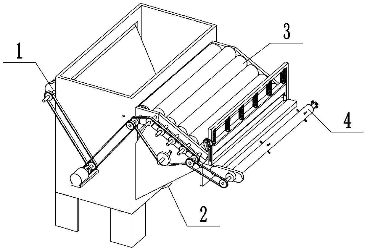
[0037] Combine below Figure 1-22 In this embodiment, a dyeing cloth bundling equipment includes a dyeing cloth assembly 1, a stirring assembly 2, a drying assembly 3 and a bundling assembly 4, and the dyeing cloth assembly 1 and the stirring assembly 2 are Connection, the drying assembly 3 is connected with the dyeing assembly 1, and the bundling assembly 4 is connected with the drying assembly 3.

specific Embodiment approach 2

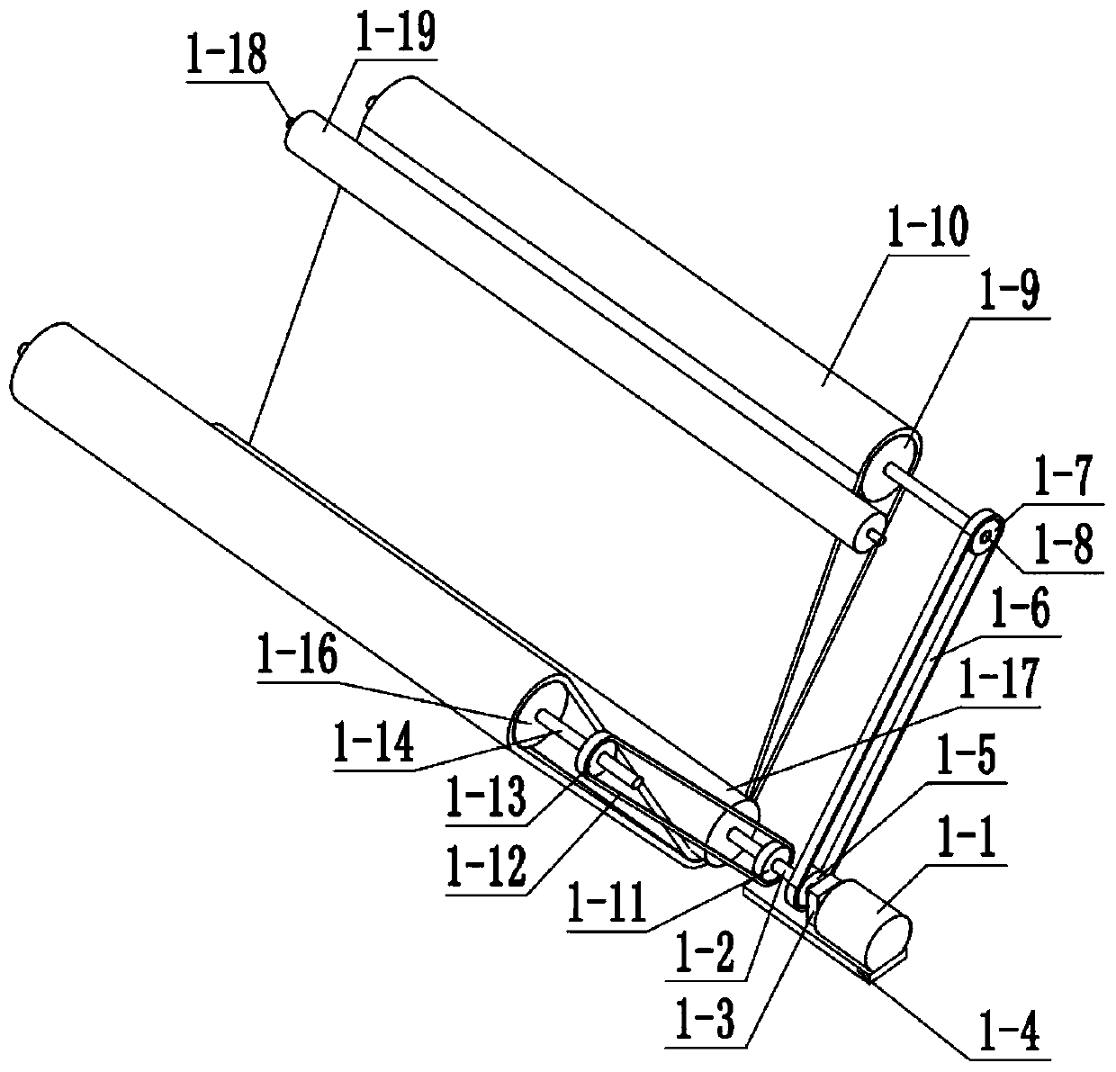
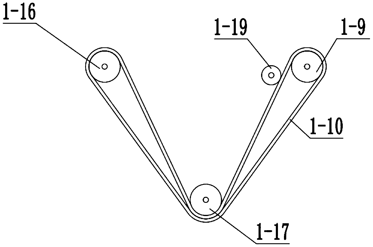
[0039] Combine below Figure 1-22 In this embodiment, this embodiment will further explain Embodiment 1. The dyeing cloth assembly 1 includes a motor I 1-1, a motor I shaft 1-2, a motor I shaft bracket 1-3, a motor I bracket 1-4, Dyeing sprocket Ⅰ1-5, dyeing chain Ⅰ1-6, dyeing sprocket Ⅱ1-7, dyeing shaft Ⅰ1-8, dyeing roller Ⅰ1-9, conveyor belt 1-10, dyeing sprocket Ⅲ1- 11. Dyeing chain Ⅱ1-12, dyeing sprocket Ⅳ1-13, dyeing shaft Ⅱ1-14, dyeing shaft Ⅱ support 1-15, dyeing roller Ⅱ1-16, dyeing roller Ⅲ1-17, extrusion Water shaft 1-18 and squeeze roller 1-19, motor I 1-1 is connected with motor I shaft 1-2, motor I 1-1 is connected with motor I bracket 1-4, motor I shaft 1-2 is connected with motor I Shaft support 1-3 is rotationally connected, motor I shaft support 1-3 is connected with motor I support 1-4, motor I shaft 1-2 is connected with dyeing cloth sprocket I1-5, dyeing cloth sprocket I1-5, Dyeing chain Ⅰ1-6, dyeing sprocket Ⅱ1-7 are connected by sprocket chain, dyeing s...

specific Embodiment approach 3

[0041] Combine below Figure 1-22 This embodiment, this embodiment will further explain the first embodiment, the stirring assembly 2 includes motor II 2-1, motor II bracket 2-2, dyeing chamber bottom plate 2-3, dyeing chamber 2-4, motor II shaft 2-5. Stirring sprocket Ⅰ 2-6, stirring chain 2-7, stirring sprocket Ⅱ 2-8, stirring shaft 2-9 and stirring blade 2-10, motor Ⅱ 2-1 is connected with motor Ⅱ bracket 2-2, The motor II bracket 2-2 is connected to the dyeing chamber bottom plate 2-3, the dyeing chamber bottom plate 2-3 is connected to the dyeing chamber 2-4, the motor I shaft 1-2, and the water squeezing shaft 1-18 are all connected to the dyeing chamber 2- 4 Rotation connection, motor I support 1-4, dyeing shaft II support 1-15 are connected with dyeing chamber 2-4, motor II shaft 2-5 is connected with motor II 2-1, motor II shaft 2-5 is connected with Dyeing room bottom plate 2-3 is rotationally connected, motor II shaft 2-5 is connected with agitating sprocket I2-6, ...


PUM


Abstract

The invention relates to the field of textile, in particular to dyed cloth bundling equipment. During cloth dyeing, waste is often caused by dripping of dye, drying of dyed cloth wastes time, and processes of dyeing, drying and bundling cannot be automatically completed. The problems are solved in the invention, cloth to be dyed is fixed at one end of a conveying belt, and enters a dyeing chamberalong with the conveying belt, the dye in the dyeing chamber is uniformly stirred by stirring blades without different colors, and excess dye on the cloth is squeezed off by a squeezing roller and falls into the dyeing chamber. After the cloth is dyed, the cloth is scraped from the conveying belt by a scraper, and the cloth is dried thoroughly by a heating wire, then the equipment stops working, acloth bobbin sleeves a cloth winding barrel, a pull handle is pulled to extend a supporting column, the cloth bobbin is fixed, the cloth which is dried thoroughly is fixed on the cloth bobbin, the equipment starts working again, the cloth winding barrel drives the cloth bobbin to rotate to wind the cloth, a shifting wheel is shifted, a cutter resets after dropping down, then the cloth can be cutinto sections, and thus, the processes of dyeing, drying and bundling are finished automatically.

Description

technical field [0001] The invention relates to a textile field, in particular to a dyed cloth bundling equipment. Background technique [0002] During the cloth dyeing operation, it is often encountered that the dye of the dyed cloth drips to cause waste, and the dyed cloth is wasted time in drying, and the processes of dyeing, drying, and bundling cannot be completed automatically. The present invention solves the above problems. Contents of the invention [0003] The purpose of the present invention is achieved through the following technical solutions: [0004] A kind of bundling equipment for dyed cloth, including a dyed cloth assembly, a stirring assembly, a drying assembly and a bundling assembly, characterized in that: the dyeing cloth assembly is connected to the stirring assembly, and the drying assembly The body is connected with the dyeing cloth assembly, and the bundling assembly is connected with the drying assembly. [0005] As a further optimization of th...

Claims


Application Information

Patent Timeline
IPC IPC(8): D06B3/10D06B15/02D06B15/08D06B15/00D06B23/04D06H7/02
CPCD06B3/10D06B15/00D06B15/02D06B15/08D06B23/04D06H7/02
Inventor 王金英许文星
Owner 王金英
Features
  • R&D
  • Intellectual Property
  • Life Sciences
  • Materials
  • Tech Scout
  • Unparalleled Data Quality
  • Higher Quality Content
  • 60% Fewer Hallucinations
Learn More