Supercharge Your Innovation With Domain-Expert AI Agents!

Low-voltage switchgear drawer position interlocking mechanism

A low-voltage switchgear and interlocking mechanism technology, applied in switchgear, pull-out switchgear, electrical components, etc., can solve problems such as the lack of mechanical interlocking structure of drawers and the inability to prevent drawers from being pulled out accidentally.

Active Publication Date: 2021-01-08
广东正超电气有限公司
View PDF10 Cites 0 Cited by
  • Summary
  • Abstract
  • Description
  • Claims
  • Application Information

AI Technical Summary

Problems solved by technology

[0006] Although the above-mentioned drawer structure solves the problem of the gap between the drawer panel and the circuit compartment frame, there are still the following problems: when the drawer is in the test state (test position) or working state (working position), in the case of misoperation, It is still possible to accidentally pull the entire drawer (including drawer body and electrical component module assembly) out by pulling on the drawer front
In other words, the above-mentioned drawers lack a reliable mechanical interlocking structure, which cannot prevent the drawers from being accidentally pulled out in the test state or working state, so there are still potential safety hazards

Method used


Image

  • Low-voltage switchgear drawer position interlocking mechanism
  • Low-voltage switchgear drawer position interlocking mechanism
  • Low-voltage switchgear drawer position interlocking mechanism

Examples


Embodiment Construction

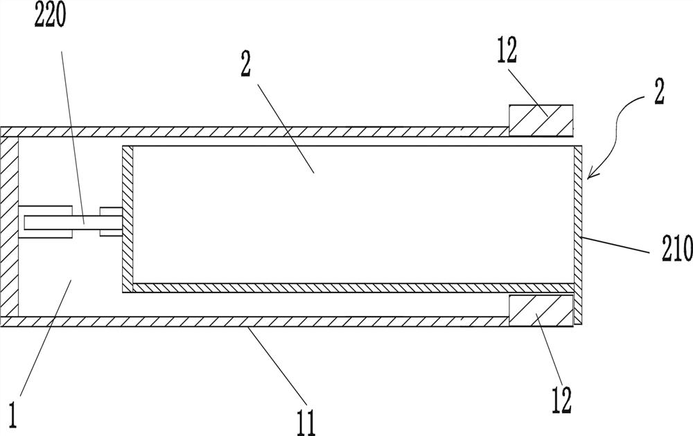
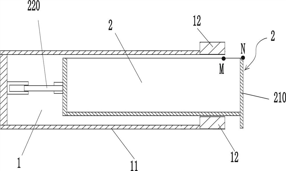
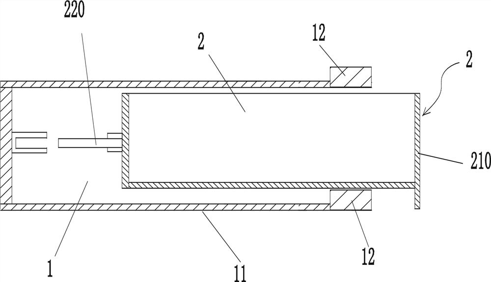
[0058] Figure 4 , Figure 5 , Figure 6 , Figure 10 As shown, the low-voltage switchgear drawer position interlocking mechanism of this embodiment includes a circuit compartment, and the circuit compartment is provided with a compartment laminate, and each circuit compartment is correspondingly equipped with a drawer 2, and each drawer 2 is located in the corresponding compartment Above the laminate 11, the drawer 2 is divided into two parts: the drawer main body 21 and the electrical component module assembly 22. Limited relative longitudinal movement can occur between the two parts, and the drawer is also provided with a drive electrical component module 22 assembly relative to the drawer main body. 21 A screw mechanism 23 that moves longitudinally. The screw mechanism 23 is provided with a screw mechanism drive rod 230; the drawer body 21 includes a drawer panel 210, and the electrical component module assembly 22 is provided with a plug-in 220, which is divided into a ...


PUM


Abstract

The invention relates to a drawer position interlocking mechanism of a low-voltage switch cabinet. The drawer position interlocking mechanism comprises loop compartments provided with compartment laminating plates. Each loop compartment is correspondingly provided with a drawer; each drawer is divided into a main drawer body and an electrical element module assembly; the main drawer body can be vertically and slidably provided with a spring bolt block; and lock holes are correspondingly formed in the compartment laminating plates. A swing plate is installed at the main drawer body in a horizontal swing manner; the electrical element module assemblies are fixedly connected with inclined plates; and vertical pins of the swing plates abut against edges of sides of the inclined plates. A capsule-shaped lock cylinder block is arranged between the swing plate and the spring bolt block; an arc section is formed at the edge of one side, being close to the capsule-shaped lock cylinder block, ofthe swing plate; an arc notch is formed in the middle of the arc section of the swing plate; and an arc groove in which a hemispherical end part of the capsule-shaped lock cylinder block is embeddedis formed in the side surface, facing the capsule-shaped lock cylinder block, of the lock spring block. Therefore, a phenomenon that a drawer in a testing state or working state is drawn out of the loop compartment accidentally is prevented.

Description

technical field [0001] The invention belongs to the technical field of power switch cabinets, and in particular relates to a drawer position interlocking mechanism of a low-voltage switch cabinet. Background technique [0002] The low-voltage switchgear can be designed as a drawer type, such as figure 1 , figure 2 , image 3 As shown, it includes a plurality of circuit compartments 1, and the circuit compartment 1 is provided with a compartment laminate 11, and each circuit compartment 1 is correspondingly equipped with a drawer 2, and the drawer 2 is located above the corresponding compartment laminate 11, and the drawer 2 Driven by the screw mechanism to produce longitudinal movement; the front (front) of the drawer 2 is provided with a drawer panel 210, and the rear end of the drawer 2 is provided with a plug-in 220. The plug-in is divided into a primary plug-in and a secondary plug-in, and the rear end of the circuit compartment corresponds to There are primary socke...

Claims


Application Information

Patent Timeline
Patent Type & Authority Patents(China)
IPC IPC(8): H02B11/133H02B11/173
CPCH02B11/133H02B11/173
Inventor 吴厚烽吴汉榕庄楚明张秀梅黄顺得蔡汉标吴炎俊郑侨培
Owner 广东正超电气有限公司
Features
  • R&D
  • Intellectual Property
  • Life Sciences
  • Materials
  • Tech Scout
  • Unparalleled Data Quality
  • Higher Quality Content
  • 60% Fewer Hallucinations
Learn More