Supercharge Your Innovation With Domain-Expert AI Agents!

Life Prediction Method of Conveyor Belt

A technology for life prediction and conveyor belts, used in testing wear resistance and other directions

Inactive Publication Date: 2020-11-13
THE YOKOHAMA RUBBER CO LTD
View PDF8 Cites 0 Cited by
  • Summary
  • Abstract
  • Description
  • Claims
  • Application Information

AI Technical Summary

Problems solved by technology

However, the wear pattern of the covering rubber has a complex relationship with various factors, so further improvement and research are required in order to predict the life of the conveyor belt more accurately and simply.

Method used


Image

  • Life Prediction Method of Conveyor Belt
  • Life Prediction Method of Conveyor Belt
  • Life Prediction Method of Conveyor Belt

Examples


Embodiment Construction

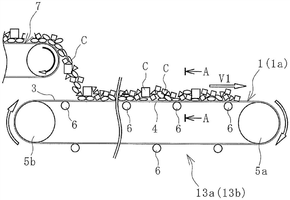
[0023] Hereinafter, the life prediction method of the conveyor belt of this invention is demonstrated based on embodiment shown in a figure.

[0024] exist figure 1 In the conveyor belt operation line exemplified in , the conveyed objects C conveyed by other conveyer belts 7 are put into the conveyer belt 1 and conveyed to the conveyance destination by the conveyer belt 1 . The conveyed object C may also be thrown into the conveyor belt 1 through a hopper or the like. The conveyor belt 1 is stretched between the pulleys 5a, 5b and tensioned at a predetermined tension.

[0025] Such as figure 2 As illustrated, the conveyor belt 1 is composed of a core layer 2 made of a core such as canvas and steel cord, and an upper cover rubber 3 and a lower cover rubber 4 sandwiching the core layer 2 . The core layer 2 is a member that receives tension for tension setting the conveyor belt 1 . On the carrier side of the conveyor belt 1 , the lower cover rubber 4 is supported by backup r...


PUM


Abstract

Provided is a conveyor belt life prediction method that makes it possible to more simply and highly accurately predict a life that is dependent on upper rubber cover wear. In this method, a wear pattern database is created for wear patterns Ps formed on each rubber test sample in each wear test method. A wear speed correlation database is created for standard wear speed characteristics obtained through the use of each type of rubber on a standard conveyor line 13a and the wear speed characteristics of each test sample. The wear test method that creates the wear pattern most similar to an evaluation wear pattern Pr created on an upper rubber cover 3 after a conveyor belt 1a to be evaluated has been used for a prescribed period on a given conveyor line 13a is specified from the wear pattern database. The wear speed characteristic of the upper rubber cover 3 on the conveyor belt 1a on the conveyor line 13a is ascertained through the adjustment of the wear speed correlation database for the specified test method according to the severity of the conveyor line 13a.

Description

technical field [0001] The present invention relates to a method for predicting the life of a conveyor belt, and more specifically, to a method for predicting the life of a conveyor belt capable of predicting the life due to wear of an upper cover rubber more accurately and simply. Background technique [0002] Various items including mineral resources such as iron ore and limestone are transported on conveyor belts. In the case of conveying goods by a conveyor belt, the conveyed material is thrown into the top cover rubber of the conveyor belt from a hopper or other conveyor belts. The input conveyed goods are stowed on the upper cover rubber and conveyed in the direction of travel of the conveyor belt. When a conveyed object is loaded on the top cover rubber for conveyance, the conveyed object slides on the top cover rubber, and the top cover rubber wears out. The amount of wear and the wear pattern caused by the rubber covering the upper surface of the conveyor belt var...

Claims


Application Information

Patent Timeline
Patent Type & Authority Patents(China)
IPC IPC(8): G01N3/56
CPCG01N3/56
Inventor 邹德庆铃木悦子
Owner THE YOKOHAMA RUBBER CO LTD
Features
  • R&D
  • Intellectual Property
  • Life Sciences
  • Materials
  • Tech Scout
  • Unparalleled Data Quality
  • Higher Quality Content
  • 60% Fewer Hallucinations
Learn More