Check patentability & draft patents in minutes with Patsnap Eureka AI!

A central air-conditioning heat recovery device

A technology for central air conditioning and heat energy recovery, which is applied in energy recovery systems for ventilation and heating, air conditioning systems, space heating and ventilation, etc. and other problems, to achieve good utilization effect, improve heat exchange efficiency, and increase the effect of contact area

Inactive Publication Date: 2021-06-25
SHANDONG DESING ARTIFICIAL ENVIRONMENT CO LTD
View PDF6 Cites 0 Cited by
  • Summary
  • Abstract
  • Description
  • Claims
  • Application Information

AI Technical Summary

Problems solved by technology

[0002] When the central air conditioner is in cooling operation, it must emit a large amount of condensed waste heat gas to the outside through the condenser. Most of the existing central air conditioners do not effectively use this part of the condensed waste heat gas when they are designed, but directly discharge it to In the atmosphere, this part of the condensed waste heat gas cannot be effectively used, resulting in a waste of energy

Method used


Image

  • A central air-conditioning heat recovery device
  • A central air-conditioning heat recovery device
  • A central air-conditioning heat recovery device

Examples


Embodiment 1

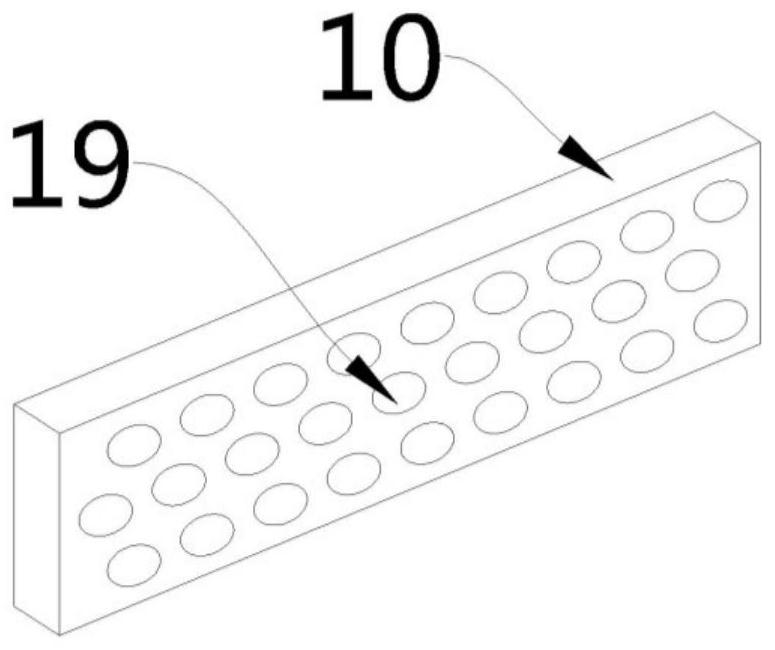
[0024] see Figure 1-3 , this embodiment provides a central air-conditioning heat recovery device, including an outer box 1 and an inner box 2 arranged inside the outer box 1, an air storage chamber 5 is arranged between the outer box 1 and the inner box 2, and the inner box The top of the box 2 is against the top wall of the outer box 1, the upper part of the inner box 2 is provided with a water drop channel 8, the upper part of the outer box 1 is provided with a water injection port 7, and the upper part of one side of the outer box 1 is pierced with an air intake pipe 11, and the outer box 1 The side is provided with an exhaust port 17, and one end of the air intake pipe 11 is connected to the central air conditioner condenser (not shown), and the other end is communicated with a gas splitter plate 10, and the end of the gas splitter plate 10 away from the intake pipe 11 is opened There is an air inlet 19, and the air inlet 19 is connected with a shunt pipe 9, and the shunt...

Embodiment 2

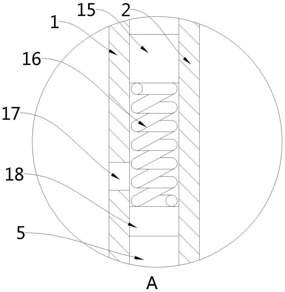
[0033] see figure 1 and figure 2 , a central air-conditioning heat recovery and utilization device. Compared with Embodiment 1, the air storage chamber 5 in this embodiment is fixedly provided with a support block 15, the support block 15 is located above the exhaust port 17, and the support block 15 The bottom is connected with a top block 18 through a spring 16, and when the spring stretches naturally, the top block 18 is located below the exhaust port 17.

[0034] As the shunt pipe 9 continues to inject hot air into the interior of the gas storage chamber 5, the internal pressure of the gas storage chamber 5 gradually increases. When the internal pressure of the gas storage chamber 5 increases to a certain level, the top block 18 is lifted upwards, The spring 16 is under pressure, and when the top block 18 moves to the exhaust port 17 , the hot air inside the air storage chamber 5 is discharged from the exhaust port 17 .

[0035] Through the setting of the support block ...


PUM


Abstract

The invention provides a central air-conditioning heat energy recycling device, belonging to the technical field of energy-saving equipment, comprising an outer box and an inner box arranged inside the outer box, an air storage chamber is arranged between the outer box and the inner box, and the top of the inner box Against the top wall of the outer box, the upper part of the inner box is provided with a drain channel, the upper part of the outer box is provided with a water injection port, the upper part of one side of the outer box is pierced with an air intake pipe, and one side of the outer box is provided with an exhaust port. The embodiment of the present invention has a good utilization effect on the hot air flow generated by the central air conditioner. Through the arrangement of the gas distribution plate and the distribution pipe, the contact area with the water can be increased, and the heat exchange efficiency between the hot air flow and water can be improved. The water inside the inner box is pumped into the pipeline, output through the through hole at the bottom of the pipeline, and then exchanges heat with the shunt pipe again to further improve the heat exchange efficiency between the hot air flow and water; the hot air flow output through the shunt pipe enters the interior of the air storage chamber, The inner box is insulated to effectively prevent the loss of heat in the inner box.

Description

technical field [0001] The invention belongs to the technical field of energy-saving equipment, in particular to a central air-conditioning heat recovery and utilization device. Background technique [0002] When the central air conditioner is in cooling operation, it must emit a large amount of condensed waste heat gas to the outside through the condenser. Most of the existing central air conditioners do not effectively use this part of the condensed waste heat gas when they are designed, but directly discharge it to In the atmosphere, this part of the condensed waste heat gas cannot be effectively used, resulting in a waste of energy. Contents of the invention [0003] In view of the above-mentioned deficiencies in the prior art, the technical problem to be solved by the embodiments of the present invention is to provide a central air-conditioning heat recovery and utilization device. [0004] In order to solve the problems of the technologies described above, the prese...

Claims


Application Information

Patent Timeline
Patent Type & Authority Patents(China)
IPC IPC(8): F24F12/00F24F13/20F24F13/30
CPCF24F12/00F24F13/20F24F13/30
Inventor 杜秀月杜秀拴杜秀杰郭怀德
Owner SHANDONG DESING ARTIFICIAL ENVIRONMENT CO LTD
Features
  • R&D
  • Intellectual Property
  • Life Sciences
  • Materials
  • Tech Scout
  • Unparalleled Data Quality
  • Higher Quality Content
  • 60% Fewer Hallucinations
Learn More