Lubricating oil processing device, lubricating oil processing method and lubricating oil
A technology for processing equipment and lubricating oil, applied in the directions of lubricating compositions, chemical instruments and methods, transportation and packaging, etc., can solve the problems of impurity removal, inability to stir lubricating oil, etc.
- Summary
- Abstract
- Description
- Claims
- Application Information
AI Technical Summary
Problems solved by technology
Method used
Image

Examples
specific Embodiment approach 1
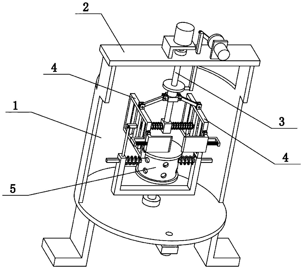
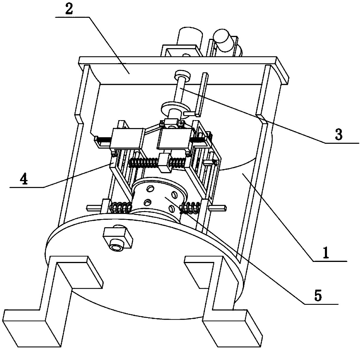
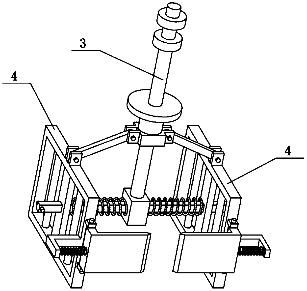
[0035] Combine below Figure 1-10 Describe this embodiment, the present invention relates to the field of lubricating oil processing, more specifically, a lubricating oil processing device, including a stirring shaft 3, a bottom block 302, a horizontal column 303, a stop pin 304, a middle slider 305, and a hinged rod 306 , the rectangular frame 4, the middle plate 402 and the hinged seat 407, the present invention can effectively stir and remove the lubricating oil.
[0036]The lower part of the stirring shaft 3 is fixedly connected with a bottom block 302, the left and right sides of the bottom block 302 are fixedly connected with a cross column 303, and the outer ends of the two cross posts 303 are fixedly connected with a retaining pin 304, and the stirring shaft 3 slides A middle slider 305 is connected, and the left and right sides of the middle slider 305 are hingedly connected with hinged rods 306. There are two rectangular frames 4 left and right, and the middle parts ...
specific Embodiment approach 2
[0038] Combine below Figure 1-10 To illustrate this embodiment, the lubricating oil processing device further includes a stirring rod 401 , and a plurality of stirring rods 401 are fixedly connected to the two rectangular frames 4 . The multiple stirring rods 401 of the two rectangular frames 4 improve the stirring effect of the two rectangular frames 4 .
specific Embodiment approach 3
[0040] Combine below Figure 1-10 To illustrate this embodiment, the lubricating oil processing device further includes an L-shaped column 403, a friction plate 404, a triangular tip 405, and a hinge plate 406, and the front ends of the two rectangular frames 4 are hingedly connected to the hinge plate 406, and the two hinge plates Friction plates 404 are fixedly connected to 406, and the two friction plates 404 are arranged opposite to each other. The inner ends of the two friction plates 404 are provided with triangular pointed heads 405, and the front ends of the two rectangular frames 4 are fixedly connected with L-shaped columns 403. One ends of the two springs are respectively fixedly connected to the two L-shaped columns 403, and the other ends of the two springs are respectively fixedly connected to the two hinge plates 406; the front and rear end surfaces of the two friction plates 404 are rough surfaces. When the two rectangular frames 4 approach and move away from e...
PUM
 Abstract
Description
Claims
Application Information
 - R&D Engineer
- R&D Manager
- IP Professional
- Industry Leading Data Capabilities
- Powerful AI technology
- Patent DNA Extraction
Browse by: Latest US Patents, China's latest patents, Technical Efficacy Thesaurus, Application Domain, Technology Topic.
© 2024 PatSnap. All rights reserved.Legal|Privacy policy|Modern Slavery Act Transparency Statement|Sitemap