Cooling device used for manufacturing plastic product

A technology for cooling devices and products, applied in the field of cooling devices used in the manufacture of plastic products, can solve the problems of difficult water temperature control, product quality decline, easy agglomeration of particles, etc., and achieve the effect of avoiding excessive temperature

Pending Publication Date: 2020-03-27
株洲瑞尔泰机电科技有限公司
View PDF10 Cites 0 Cited by
  • Summary
  • Abstract
  • Description
  • Claims
  • Application Information

AI Technical Summary

Problems solved by technology

[0003] There are certain deficiencies in this single sink: first, the water temperature is not easy to control
The strip needs to be cooled by the cooling water tank before it can be pelletized. If the cooling water temperature is too low, the pellets cut by the pelletizer will produc

Method used


Image

  • Cooling device used for manufacturing plastic product
  • Cooling device used for manufacturing plastic product
  • Cooling device used for manufacturing plastic product

Examples


Example Embodiment

[0025] Example 1

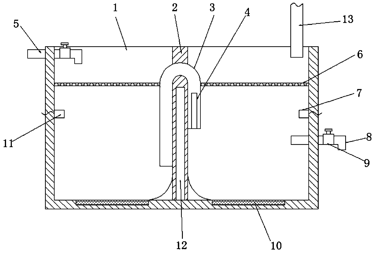
[0026] Reference Figure 1-3 , A cooling device for the manufacture of plastic products, comprising a water tank 1, a partition 2 is fixed in the water tank 1, and the partition 2 divides the interior of the water tank 1 into two water storage chambers, and the partition 2 is fixedly installed with a connecting The two ends of the pipe 3 and the connecting pipe 3 are respectively located in the two water storage chambers. The water outlet on the right side of the connecting pipe 3 is higher than the water inlet on the left side, and the outer wall of the water outlet on the right side of the connecting pipe 3 has a strip hole. 4. The heating plate 10 is fixed on the inner wall of the bottom of the two water storage chambers, and the first temperature sensor 7 and the second temperature sensor 11 are respectively provided on the side walls of the two water storage chambers, and the two water storage chambers are respectively fixedly inserted A water inlet pipe ...

Example Embodiment

[0030] Example 2

[0031] Reference Figure 4 , A cooling device used in the manufacture of plastic products. The difference between this embodiment and embodiment 1 is that symmetrically distributed motors 21 are fixed on the outer walls of both sides of the water tank 1, and the output shaft of the motor 21 passes through the inner wall of the water storage chamber and is fixed with a transmission At one end of the shaft 22 and the transmission shaft 22 away from the motor 21, a plurality of annularly distributed turbine blades 23 are fixed, and arc plates 24 are fixed on both sides of the bottom end of the partition plate 2.

[0032] The working principle of this embodiment: the arrangement of the turbine blades 23 can push the aqueous solution in the left and right water storage chambers under the drive of the motor 21, and the water flow is guided by the arc plate 24 to form the inner parts of the two water storage chambers. Water circulation to prevent the cold water from bei...


PUM


Abstract

The invention discloses a cooling device used for manufacturing a plastic product. The cooling device comprises a water tank, wherein a separation plate is fixed in the water tank and divides the inner part of the water tank into two water storage cavities; the separation plate is fixedly provided with a communication pipe; two ends of the communication pipe are independently positioned in the twowater storage cavities; the horizontal height of a water outlet end on the right side of the communication pipe is higher than a water inlet end on the left side; the outer wall of the water outlet end on the right side of the communication pipe is provided with a bar-shaped hole; the bottom inner walls of the two water storage cavities are independently fixedly provided with a heating plate; theside walls of the two water storage cavities are independently provided with a first temperature sensor and a second temperature sensor; a water inlet pipe and a water outlet pipe are independently fixedly inserted into the two water storage cavities and are independently provided with a solenoid valve; and the right top position of the water tank is provided with an exhaust mechanism. By use ofthe cooling device, a siphon principle is used for realizing the balanced work of a water temperature in the water tank so as to be convenient in use.

Description

technical field [0001] The invention relates to the technical field of cooling equipment for plastic production, in particular to a cooling device for the manufacture of plastic products. Background technique [0002] At present, when engineering plastics are produced, a single cooling water tank is mostly used. By continuously injecting cooling water into the water tank, the plastic strips extruded from the die pass through the water tank containing cooling water to achieve cooling purposes. [0003] There are certain deficiencies in this single tank: the first, the water temperature is difficult to control. The strip needs to be cooled by the cooling water tank before it can be pelletized. If the cooling water temperature is too low, the pellets cut by the pelletizer will produce stress whitening, and there will be too much plastic shavings, which will reduce the product quality; if the cooling water temperature is too high, the strip will be cut due to too hot Particles ...

Claims


Application Information

Patent Timeline
IPC IPC(8): B29C48/885B29C48/92B29C48/275
CPCB29C48/277B29C48/885B29C48/911B29C48/919B29C48/92B29C2948/92704B29C2948/92923Y02P70/10
Inventor 杨又伦曹剑覃远福刘建华
Owner 株洲瑞尔泰机电科技有限公司
Why Eureka
Try Eureka