Bridge deck slab and bridge expansion joint structure
A bridge deck and panel technology, which is applied to bridges, bridge parts, bridge construction, etc., can solve the problems of low operation efficiency, complicated connection operation process between bridge deck and anchor base, etc., and achieves simple operation process, improved operation efficiency, and convenient fixation. Effect
- Summary
- Abstract
- Description
- Claims
- Application Information
AI Technical Summary
Problems solved by technology
Method used
Image

Examples
Embodiment 2
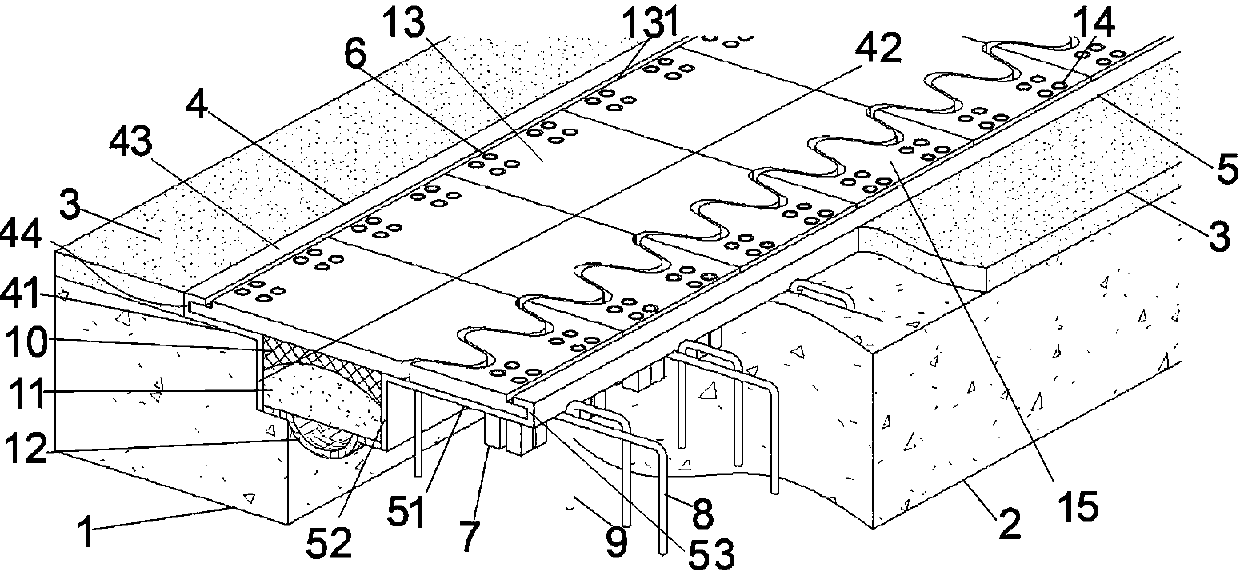
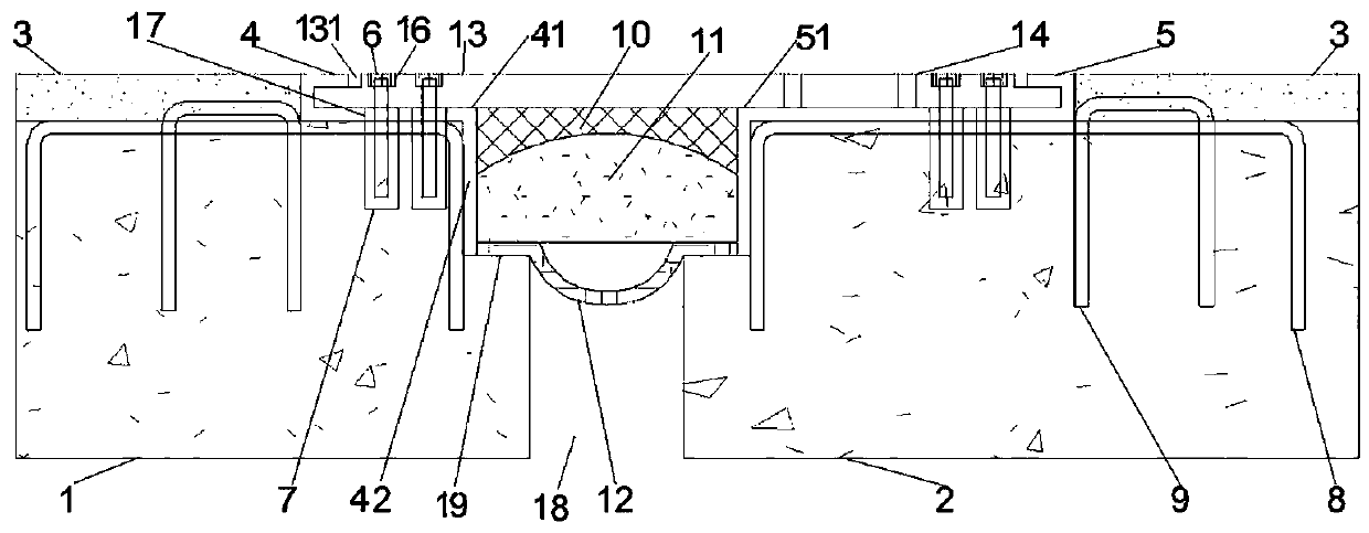
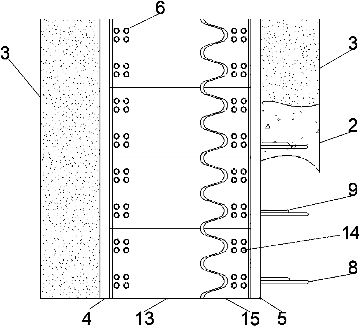
[0090] Embodiment 2 of bridge expansion joint structure in the present invention: the difference between this embodiment and embodiment 1 is that in this embodiment, as Figure 7 with Figure 8 As shown, the top surface of the elastic rubber mold 11 is a corrugated structure, which is roughly a sine wave in this embodiment. The waveform of the corrugated structure extends along the width direction of the bridge expansion joint 18. The corrugated structure has a trough and two crests, and the trough is located at In the middle of the width direction of the bridge expansion joint, the crest is located between the seam wall of the bridge expansion joint and the trough; correspondingly, the bottom surface of the elastic sealant 10 conforms to the shape of the top surface of the elastic rubber mold, and is also a corrugated structure. During the forming process of the elastic sealant 10, an auxiliary forming mold is arranged on the top surface of the elastic sealant 10, and the aux...
Embodiment 3
[0094] Embodiment 3 of a bridge telescopic device in the present invention, the difference between this embodiment and Embodiment 1 is that the bridge deck anchoring bar body in Embodiment 1 is made of steel bars, and is a U-shaped structure, while this embodiment Among them, the anchoring ribs of the bridge deck are formed by anchoring steel plates, which protrude from the edge of the horizontal steel plate, and two adjacent sides of the anchoring steel plate are respectively welded to the horizontal steel plate and the vertical steel plate of the anchoring base.
[0095] In addition, in other embodiments, the anchoring tendons of the bridge deck can also be in other shapes, such as M-shape, rectangle, and the like. Moreover, in other embodiments, the bridge deck anchoring tendons can also be provided in multiple channels along the vertical direction, and some of the bridge deck anchoring ribs can also be connected only with the horizontal steel plates of the anchor base or on...
Embodiment 4
[0096] Embodiment 4 of a bridge expansion device in the present invention, the difference between this embodiment and Embodiment 1 is that in Embodiment 1, the horizontal connection part of the bridge deck anchorage rib is provided with a pavement layer rib, and In this embodiment, no pavement reinforcement is provided on the anchorage reinforcement of the bridge deck. In other embodiments, if it is necessary to set the reinforcement body of the pavement layer, the reinforcement body of the pavement layer can also be welded and fixed to the horizontal steel plate; in addition, in other embodiments, the reinforcement body of the pavement layer can also be separated from the horizontal steel plate, The shape and quantity of the pavement layer ribs can also be changed according to needs, for example, more than two pavement layer ribs are arranged along the front and rear directions.
PUM
 Abstract
Description
Claims
Application Information
 - R&D
- Intellectual Property
- Life Sciences
- Materials
- Tech Scout
- Unparalleled Data Quality
- Higher Quality Content
- 60% Fewer Hallucinations
Browse by: Latest US Patents, China's latest patents, Technical Efficacy Thesaurus, Application Domain, Technology Topic, Popular Technical Reports.
© 2025 PatSnap. All rights reserved.Legal|Privacy policy|Modern Slavery Act Transparency Statement|Sitemap|About US| Contact US: help@patsnap.com