Remote controller for controlling aircraft

A technology of aircraft and remote control, applied in the field of remote control, can solve the problem of difficult to control the smooth flight at a uniform speed, and achieve the effect of uniform speed and steering, and smooth aerial image.

Pending Publication Date: 2020-05-01
SHENZHEN SWELLPRO TECH CO LTD
0 Cites 0 Cited by

AI-Extracted Technical Summary

Problems solved by technology

[0003] The purpose of the present invention is to provide a remote controller for controlling the aircraft, aiming to solve the technical probl...

Method used

[0044] Preferably, the first direction is in the same direction as the fifth direction, the second direction is in the same direction as the sixth direction, the third direction is in the same direction as the seventh direction, and the The fourth direction is in the same direction as the eighth direction, so as to conform to the user's usage habit and control feeling, and reduce the user's misoperation. More pr...

Abstract

The invention provides a remote controller for controlling an aircraft. The remote controller comprises a control main body, a first control rocking bar, a second control rocking bar, a first rotary knob and a second rotary knob. The first control rocking bar can start the control main body to implement ascending and descending of the aircraft. The second control rocking bar can start the controlmain body to implement moving forward and backward of the aircraft. Rotation of the first rotary knob can start the control main body to implement clockwise or anticlockwise rotation of the aircraft.Rotation of the second rotary knob can start the control main body to implement left or right translation of the aircraft. A deviation angle of the first rotary knob or the second rotary knob relativeto the first initial position is in direct proportion to a running speed of the aircraft. Both a rotational speed and a left or right translation speed of the aircraft can be fine-tuned by using thefirst rotary knob or the second rotary knob, to implement fine control over the speed of the aircraft, so that a flight speed of the aircraft is uniform, and aerial images are smoother.

Application Domain

Position/course control in three dimensions

Technology Topic

Flight vehicleAerial image +3

Image

  • Remote controller for controlling aircraft

Examples

  • Experimental program(1)

Example Embodiment

[0025] The embodiments of the present invention are described in detail below. Examples of the embodiments are shown in the accompanying drawings, in which the same or similar reference numerals indicate the same or similar elements or elements with the same or similar functions. The embodiments described below with reference to the accompanying drawings are exemplary, and are intended to explain the present invention, but should not be construed as limiting the present invention.
[0026] In the description of the present invention, it should be understood that the terms "length", "width", "upper", "lower", "front", "rear", "left", "right", "vertical", The orientation or positional relationship indicated by "horizontal", "top", "bottom", "inner", "outer", etc. is based on the orientation or positional relationship shown in the drawings, and is only for the convenience of describing the present invention and simplifying the description, not It indicates or implies that the pointed device or element must have a specific orientation, be constructed and operated in a specific orientation, and therefore cannot be understood as a limitation of the present invention.
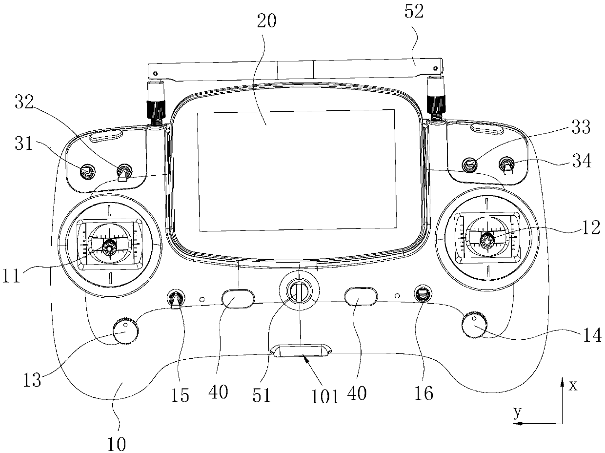
[0027] In this embodiment, figure 1 The front view of the remote control provided for the present invention, according to figure 1 The definition of the XY Cartesian coordinate system established in: the side in the positive direction of the X-axis is defined as the front, and the side in the negative direction of the X-axis is defined as the back; the side in the positive direction of the Y-axis is defined as the left, which is on the Y-axis The side in the negative direction is defined as the right.
[0028] In addition, the terms "first", "second", "third", "fourth", "fifth", "sixth", "seventh", and "eighth" are only used for descriptive purposes and cannot It is understood as indicating or implying relative importance or implicitly indicating the number of technical features indicated. Therefore, the features defined as “first”, “second”, “third”, “fourth”, “fifth”, “sixth”, “seventh”, and “eighth” can be explicitly or implicitly specified. Inclusively includes one or more of this feature. In the description of the present invention, "plurality" means two or more than two, unless specifically defined otherwise.
[0029] In the present invention, unless otherwise clearly specified and limited, the terms "installed", "connected", "connected", "fixed" and other terms should be understood in a broad sense, for example, it may be a fixed connection or a detachable connection , Or integrated; it can be a mechanical connection, or it can be an electrical connection; it can be directly connected, or indirectly connected through an intermediate medium, it can be the internal communication of two components or the interaction relationship between two components. For those of ordinary skill in the art, the specific meanings of the above terms in the present invention can be understood according to specific circumstances.
[0030] In order to make the objectives, technical solutions and advantages of the present invention clearer, the following further describes the present invention in detail with reference to the accompanying drawings and embodiments.
[0031] The invention provides a remote controller for controlling an aircraft, which is used for controlling the flight of the aircraft. The aircraft includes a flying main body, a gimbal connected to the flying main body, a camera connected to the gimbal, and a delivery device for dropping supplies.
[0032] Please refer to figure 1 The remote controller for controlling the aircraft includes a control body 10 for wireless transmission with the aircraft and controlling the flight of the aircraft, a first control rocker 11 connected to the control body 10 at one end, and One end is rotatably connected to the second control rocker 12 of the control body 10, the first knob 13 rotatably connected to the control body 10, and the second knob 14 rotatably connected to the control body 10 is used to switch the first knob. A first switch 15 for controlling the control path of the rocker 11 or the first knob 13, a second switch 16 for switching the control path of the second control rocker 12 or the second knob 14, A video transmission antenna for transmitting image signals, a display screen 20 for displaying real-time images acquired by the camera, a flight mode switch 33 for switching the flight mode of the aircraft, and a horizontal rotation control for the pan/tilt Angle of the pan/tilt tilting wheel (not shown in the figure), the tilt/tilt wheel (not shown in the figure) for controlling the tilt angle of the pan/tilt, and a battery (not shown in the figure) for powering the control body 10 Not marked in), the power switch 40 used to connect or disconnect the control body 10 and the battery, the shooting switch 32 used to control the camera to take pictures or video, and to control the delivery device to perform The dropping switch 31 for dropping action, the returning home switch 34 for controlling the intelligent returning of the aircraft, the hoisting ring 51 for hanging, and the carrying handle 52 for carrying.
[0033] Please refer to figure 1 In the embodiment of the present invention, the control main body 10 includes a housing with an accommodating cavity and a control mechanism located in the accommodating cavity, and the housing is provided with a charging interface 101 for charging the battery and A plurality of mounting holes penetrated to the accommodating cavity. The first control rocker 11 and the second control rocker 12 are rod-shaped, one ends of the two respectively pass through a mounting hole to extend into the accommodating cavity, and the other ends of the two can be respectively One end of itself extending to the inside of the accommodating cavity rotates at the center of the circle. The free ends of the first control rocker 11 and the second control rocker 12 both have starting points. When the aircraft is not started, the The free ends of the first control rocker 11 and the second control rocker 12 are both located at their starting points, and at this time, they are disconnected from the control mechanism. Preferably, the first control rocker 11 and the second control rocker 12 both have at least two degrees of freedom of rotation, leaving the starting point at the free ends of the two to the side with the degree of freedom When deflecting, a connection is established with the control mechanism to control the flight of the aircraft. More preferably, the housing is marked with a scale for measuring the rotation amplitude of the first control rocker 11 and the second control rocker 12. Further, the remote controller for controlling the aircraft further includes a rebound for making the free ends of the first remote control rocker or/and the second control rocker 12 automatically return to their respective starting points. Therefore, when the user operates the first control rocker 11 and the second control rocker 12, the position of the first control rocker 11 or the second control rocker 12 needs to be manually fixed, and the position of the first control rocker 11 or the second control rocker 12 must not be Separate.
[0034] In the embodiment of the present invention, the control mechanism has a first control state capable of controlling the ascent of the aircraft, a second control state capable of controlling the descending of the aircraft, a third control state capable of controlling the advancement of the aircraft, The fourth control state that can control the backing of the aircraft, the fifth control state that can control the counterclockwise rotation of the aircraft body, the sixth control state that can control the clockwise rotation of the aircraft body, and the The seventh control state for the aircraft to pan to the left and the eighth control state to control the aircraft to pan to the right. Wherein, the counterclockwise rotation of the aircraft fuselage means that the nose of the aircraft rotates to the left with respect to the tail. Similarly, the clockwise rotation of the aircraft fuselage means that the nose of the aircraft rotates toward the rear of the aircraft. Rotate to the right.
[0035] The first control rocker 11 can establish a connection with the control mechanism and start the first control state after the free end of the first control rocker 11 is rotated from its starting point toward the first direction, the aircraft starts to rise, and the aircraft reaches When the specified height does not need to continue to rise, the free end of the first control rocker 11 is restored to its starting point, and the aircraft stops rising; the first control rocker 11 can also move from its starting point at its free end After turning in the second direction, it establishes a connection with the control mechanism and starts the second control state. The aircraft begins to descend. When the aircraft reaches a specified height and does not need to continue descending, the first control joystick 11 The free end of the aircraft returned to its starting point and the aircraft stopped descending.
[0036] The second control rocker 12 can establish a connection with the control mechanism and start the third control state after the free end of the second control rocker 12 is rotated from its starting point toward the third direction, the aircraft starts to advance, and the aircraft reaches When the designated position does not need to continue forward, the free end of the first control rocker 11 is restored to its starting point, and the aircraft stops advancing; the second control rocker 12 can also move from its starting point at its free end After rotating in the fourth direction, it establishes a connection with the control mechanism and starts the fourth control state. The aircraft starts to retreat. When the aircraft reaches a designated position and does not need to continue to retreat, the first control joystick 11 The free end of the vehicle returned to its starting point, and the aircraft stopped retreating.
[0037] The first knob 13 has a first starting position and can establish a connection with the control mechanism and activate the fifth control state after it is rotated counterclockwise from the first starting position, and the aircraft starts to rotate counterclockwise, When it rotates counterclockwise, the offset angle relative to the first starting position is proportional to the counterclockwise rotation speed of the aircraft's fuselage. After the aircraft's fuselage rotates to a specified angle, the first The knob 13 returns to the first starting position, the first knob 13 is disconnected from the control mechanism, and the aircraft stops rotating counterclockwise; the first knob 13 moves clockwise from the first starting position. After the clockwise rotation, the connection is established with the control mechanism and the sixth control state is activated. The aircraft starts to rotate clockwise. When it rotates clockwise, the offset angle relative to the first starting position is equal to that of the fuselage of the aircraft. The clockwise rotation speed is proportional. After the fuselage of the aircraft rotates to a specified angle, the first knob 13 is restored to the first starting position, and the first knob 13 is disconnected from the control mechanism , The aircraft stops rotating clockwise. Preferably, the rotation offset of the first knob 13 counterclockwise or clockwise from the first starting position is not more than 180°. Specifically, the shell has a rotation speed scale for indicating the rotation speed of the aircraft, and the rotation speed scale is marked on the circumferential direction of the first knob 13.
[0038] The second knob 14 has a second starting position and can establish a connection with the control mechanism after it is rotated counterclockwise from the second starting position to start the seventh control state, and the aircraft starts to pan to the left , The offset angle relative to the second starting position when it rotates counterclockwise is proportional to the speed at which the aircraft translates to the left. When the aircraft does not need to move left, the second knob 14 is restored to In the second starting state, the second knob 14 is disconnected from the control mechanism, and the aircraft stops moving to the left; after the second knob 14 is rotated clockwise from the second starting position Establishing a connection with the control mechanism starts the eighth control state, the aircraft starts to translate to the right, and the offset angle of the second knob 14 relative to the second starting position when the second knob 14 rotates clockwise is the same as that of the aircraft to the right The speed of translation is proportional. When the aircraft does not need to move right, the second knob 14 is restored to the second initial state, the second knob 14 is disconnected from the control mechanism, and the The aircraft stopped moving right. Preferably, the rotation offset of the second knob 14 counterclockwise or clockwise from the second starting position is not more than 180°. Specifically, the housing is provided with a translation scale for indicating the translation speed of the aircraft, and the translation scale is marked on the circumferential direction of the second knob 14.
[0039] The offset angle of the first knob 13 relative to the first starting position when the first knob 13 of the present invention is rotated counterclockwise is proportional to the counterclockwise rotation speed of the fuselage of the aircraft, and when rotated clockwise, it is relative to the first starting position. The offset angle of the starting position is proportional to the clockwise rotation speed of the fuselage of the aircraft. When the second knob 14 is rotated counterclockwise, the offset angle relative to the second starting position is the same as that of the aircraft to the left. The speed of translation is directly proportional, and the offset angle relative to the second starting position when rotating clockwise is proportional to the speed at which the aircraft translates to the right. Therefore, both the rotation amount and the rotation speed of the aircraft can pass through the The first knob 13 quantizes and fine-tunes as required. The left and right translation speed of the aircraft can also be quantified and fine-tuned as required by the second knob 14, so that the flying amplitude and change speed of the aircraft can be controlled and achieved. With refined control, the flying speed and steering of the aircraft are more uniform, and the aerial image is smoother and smoother.
[0040] On the other hand, the first knob 13 and the second knob 14 can be fixed at the screwed position and will not automatically reset. In traditional rocker control, the user’s hand cannot leave the rocker because the rocker can automatically reset. In addition, when the joystick position is manually fixed, the control may be unstable due to slight hand shaking. Therefore, the user is required to have very rich experience to be able to control the joystick steadily to make the aircraft operate at a uniform speed. The first knob 13 and the second knob 14 overcome this technical problem and reduce the requirements for user experience. The user can intuitively understand the flight speed of the aircraft according to the twisting range, and the operation is stable. Achieve uniform flight. And because the functions of controlling the aircraft to fly up and down, fly back and forth, pan flight left and right, and rotate clockwise or counterclockwise are respectively controlled by four components, the user can control at least two components at the same time so that the aircraft can perform multiple operations simultaneously. Kind of flying maneuvers to improve flight efficiency.
[0041] Further, the first control rocker 11 can also establish a connection with the control mechanism and activate the fifth control state after the free end of the first control rocker 11 is rotated from its starting point toward the fifth direction, and the aircraft starts to rotate counterclockwise When the fuselage of the aircraft rotates to a specified angle, the free end of the first control rocker 11 is restored to its starting point, and the aircraft stops rotating counterclockwise; at its free end, the starting point faces the sixth After the direction is turned, the connection is established with the control mechanism and the sixth control state is activated. The aircraft starts to rotate clockwise. When the aircraft body rotates to a specified angle, the first control joystick 11 is set free The end returns to its starting point, and the aircraft stops rotating clockwise.
[0042] Further, the second control rocker 12 can also establish a connection with the control mechanism and activate the seventh control state after the free end of the second control rocker 12 is rotated from its starting point toward the seventh direction, and the aircraft starts to pan to the left , When the aircraft moves to the left to the designated position, the free end of the second control rocker 12 is restored to its starting point, and the aircraft stops moving to the left; at its free end, it rotates in the eighth direction from its starting point After establishing a connection with the control mechanism and starting the eighth control state, the aircraft starts to pan to the right, and when the aircraft moves to the right to a designated position, the free end of the second control rocker 12 is restored to At its starting point, the aircraft stops moving right.
[0043] In the present invention, the first control rocker 11 or the second control rocker 12 can realize the rapid operation of the left and right rotation or the left and right translation of the aircraft, and the operation experience is better.
[0044] Preferably, the first direction is the same direction as the fifth direction, the second direction is the same direction as the sixth direction, the third direction is the same direction as the seventh direction, and the fourth direction It is in the same direction as the eighth direction, so as to conform to the user's usage habits and control feel, and reduce the user's misoperation. More preferably, the first direction and the fifth direction are forward, the second direction and the sixth direction are rearward, the third direction and the seventh direction are leftward, and the fourth direction is And the eighth direction to the right. The rotation direction of each rocker is in the same direction or is related to the flying direction of the aircraft, which is easy for the user to remember and reduce misoperation.
[0045] Further, in the embodiment of the present invention, the first switch 15 has a first open state capable of cutting off the connection path of the first control rocker 11 to activate the fifth control state and the sixth control state And cutting off the first closed state of the connection path of the first knob 13 to activate the fifth control state and the sixth control state, and the second switch 16 has the ability to cut off the activation of the second control rocker 12 The second open state of the connection path of the seventh control state and the eighth control state and the second closed state of the connection path of the seventh control state and the eighth control state by turning off the second knob 14
[0046] Understandably, when the first switch 15 is in the first open state, the user can control the free end of the first control rocker 11 from its starting point toward the first direction or the Rotate in the second direction to activate the first control state or the second control state respectively. At this time, the activation of the fifth control state and the sixth control state is completed by the first knob 13, and the first control state A control rocker 11 cannot be activated; when the first switch 15 is in the first closed state, the user can control the free end of the first control rocker 11 from its starting point toward the first Direction, the second direction, the fifth direction, or the sixth direction to activate the first control state, the second control state, the fifth control state, or the sixth control state, respectively, When the fifth control state and the sixth control state are activated, the first control rocker 11 is completed, and the first knob 13 cannot be activated. When the second switch 16 is in the second open state, the user can control the free end of the second control rocker 12 to rotate from its starting point toward the third direction or the fourth direction In order to activate the third control state or the fourth control state respectively, the activation of the seventh control state and the eighth control state is completed by the second knob 14, and the second control rocker 12 can not be activated; when the second switch 16 is in the second closed state, the user can control the free end of the second control rocker 12 from its starting point toward the third direction, the Rotate in the fourth direction, the seventh direction, or the eighth direction to respectively activate the third control state, the fourth control state, the seventh control state, or the eighth control state, and at this time, the first control state The activation of the seventh control state and the eighth control state is completed by the second control rocker 12, and the second knob 14 cannot be activated.
[0047] In this way, through the opening or closing of the first switch 15 and the second switch 16, the selection of the components that control the left and right rotation of the aircraft nose and the left and right translation of the aircraft is realized. In actual use The user can adjust the first switch 15 and the second switch 16 according to needs and flight requirements of the aircraft to make the aircraft achieve the best flight state.
[0048] The above descriptions are only preferred embodiments of the present invention and are not intended to limit the present invention. Any modification, equivalent replacement and improvement made within the spirit and principle of the present invention shall be included in the protection of the present invention. Within range.

PUM

no PUM

Description & Claims & Application Information

We can also present the details of the Description, Claims and Application information to help users get a comprehensive understanding of the technical details of the patent, such as background art, summary of invention, brief description of drawings, description of embodiments, and other original content. On the other hand, users can also determine the specific scope of protection of the technology through the list of claims; as well as understand the changes in the life cycle of the technology with the presentation of the patent timeline. Login to view more.
Why Eureka
Try Eureka