Light-emitting sign with light-transmitting function and manufacturing method of light-emitting signboard

A manufacturing method and technology of signs, which are applied in the directions of illuminated signs, instruments, display devices, etc., can solve the problem that metal luminous signs cannot achieve high uniformity and no chromatic aberration lighting effect, etc., so as to improve the utilization rate of light energy and reduce the Heat dissipation burden and the effect of improving light efficiency

Active Publication Date: 2020-05-15
长春星瑞技术服务有限公司
View PDF12 Cites 3 Cited by
  • Summary
  • Abstract
  • Description
  • Claims
  • Application Information

AI Technical Summary

Problems solved by technology

[0006] The purpose of the present invention is to provide a light-emitting signage device with metal light-transmitting function to solve the technical problem

Method used


Image

  • Light-emitting sign with light-transmitting function and manufacturing method of light-emitting signboard
  • Light-emitting sign with light-transmitting function and manufacturing method of light-emitting signboard
  • Light-emitting sign with light-transmitting function and manufacturing method of light-emitting signboard

Examples


Example Embodiment

[0053] Example 1:

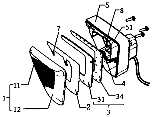
[0054] The nano-scale metal plating layer is coated on the inner surface of the transparent component 12.

Example Embodiment

[0055] Example 2:

[0056] Such as Figure 5 As shown, the surface light source module optical panel 31 includes a bottom optical structure layer 311 and an upper optical structure layer 312. The bottom optical structure layer 311 is a reflective microstructure, and the structural characteristics of its bumps can project the light beam to the bottom layer. Reflected out, thereby improving the utilization of light efficiency. Since the light beam emitted by the LED light source has a Gaussian distribution, bright spots will be generated at the center of the beam, thereby reducing the overall uniformity. The upper optical structure layer 312 includes optically uniform microstructures and bright spot shielding Therefore, the upper optical structure layer 312 on the upper surface of the optical panel 31 of the surface light source module can achieve the effect of hiding the bright spots of the light spot, thereby making the light distribution more uniform.

Example Embodiment

[0057] Example 3:

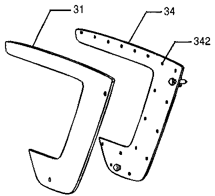
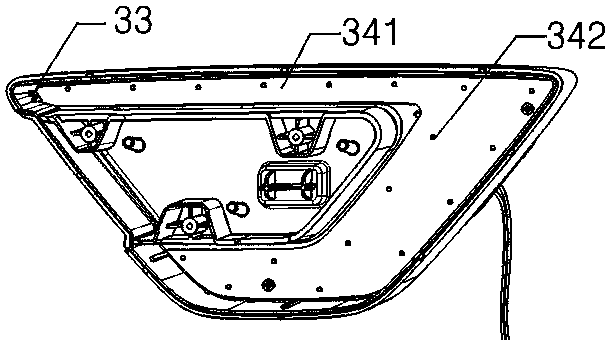
[0058] Such as Image 6 As shown, the optical system 3 includes a reflective bowl 35 and a circuit board 34, the reflective bowl 35 is arranged in an array, the focal length of the reflective bowl 35 is between 3mm-4mm, the spacing is 20mm-26mm, and the height of the reflective bowl 35 is 10mm-18mm. The distance from the diffuser 2 is greater than 10 mm.

[0059] A method for manufacturing the light-emitting sign with the light-transmitting function, the nano-level metal coating is realized by the PVD vacuum sputtering coating method, and the light transmittance is controlled between 10%-20% by adjusting the thickness of the nano-level metal coating .

[0060] In this embodiment, the reflection coefficient of the light-transmitting component 12 is 80%, the light transmission coefficient is 15%, the absorption coefficient is 5%, and the tolerance is ±5%.

[0061] In this embodiment, the reflection coefficient of the diffuser 2 is 25%, the light transmission coeffic...


PUM

PropertyMeasurementUnit
Focal lengthaaaaaaaaaa

Abstract

The invention discloses a light-emitting sign with a light-transmitting function and a manufacturing method thereof, belongs to the technical field of vehicle lamp illumination, and particularly relates to a light-emitting sign and a manufacturing method thereof. The light-emitting sign comprises a mask set, a diffusion plate, an optical system, a wire harness and a shell, and the mask set is detachably connected with the shell; the interior of the mask set and the interior of the shell jointly form a containing cavity, the optical system is arranged in the containing cavity, the wire harnessextends from the exterior of the shell to the containing cavity, and the wire harness is electrically connected with the optical system. The mask set comprises a light-transmitting component and a shading component. The light-transmitting part is coated with a nanoscale metal plating layer; the nanoscale metal coating is achieved through a PVD vacuum sputtering coating method, and the light transmittance is controlled to range from 10% to 20% by adjusting the thickness of the nanoscale metal coating. The light effect that the electroplated appearance label can be lightened after being electrified is achieved, and particularly when a white light source is adopted in an optical system of the device, the lightened light effect of the light-emitting label device still emits white light and hasno chromatic aberration phenomenon.

Description

technical field [0001] The invention belongs to the technical field of vehicle lamps, and in particular relates to a luminous signboard and a manufacturing method thereof. Background technique [0002] As a brand exterior decoration, the car logo is an indispensable accessory for the car. The car logo represents the car brand and product image, and has a unique shape design. With the rapid development of the automobile industry, the existing car logo is not only beautiful but also has a luminous function. [0003] For traditional car logos, its electroplating appearance has a high degree of brand recognition in the daytime with sufficient light. However, in an environment with insufficient light, it is difficult to display, thus losing its effect of displaying the brand image. Under such a background, it becomes an inevitable trend of future development to realize the function of the car logo that can be illuminated at night or in a dark environment. [0004] The luminous...

Claims


Application Information

Patent Timeline
IPC IPC(8): G09F13/04B60R13/00
CPCB60R13/005G09F13/0404G09F13/0413G09F13/0445
Inventor 董辉王伟明迟守利王钲强马洁周佩禹
Owner 长春星瑞技术服务有限公司
Why Eureka
Try Eureka