Check patentability & draft patents in minutes with Patsnap Eureka AI!

Electrical pump drive for positive displacement pump, positive displacement pump and method therefor

A technology of electric pumps and drivers, applied in the direction of pumps, piston pumps, pump components, etc., to achieve the effect of simple structure, cheap control, and simple structure

Inactive Publication Date: 2020-05-15
尼得科GPM有限公司
View PDF4 Cites 0 Cited by
  • Summary
  • Abstract
  • Description
  • Claims
  • Application Information

AI Technical Summary

Problems solved by technology

Based on this assessment, therefore, there is room for improvement in all aspects

Method used


Image

  • Electrical pump drive for positive displacement pump, positive displacement pump and method therefor
  • Electrical pump drive for positive displacement pump, positive displacement pump and method therefor
  • Electrical pump drive for positive displacement pump, positive displacement pump and method therefor

Examples


Embodiment Construction

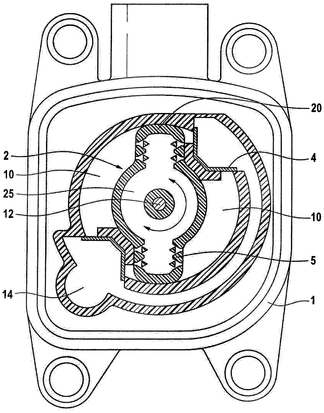
[0061] First, refer to figure 1 The construction of an exemplary oscillating piston pump for an oil pump in a low-pressure lubrication system is described, wherein the pump is equipped with an embodiment of the electric pump drive according to the invention. This oscillating piston pump is also the subject of another patent application filed at the same time by the same applicant as the present application and is described in more detail therein.

[0062] figure 1 Two diametrically opposite sector-shaped working chambers 10 are shown at the top left and bottom right of the pivot 12 , which extend in the pump housing 1 in the plane of the pivotal movement of the oscillating piston 2 . The sides of the working chamber 10 form thrust surfaces for the oscillating piston 2 .

[0063] It is shown that, above and to the left of the pivot 12 , two areas of the pump outlet 14 are arranged between the working chambers 10 and are connected by an arcuate channel in the pump housing 1 . ...


PUM


Abstract

The invention relates to an electrical pump drive for positive displacement pumps having pistons moved in an oscillating manner. The electrical pump drive is characterised in that the electrical pumpdrive comprises a rotary magnet (3) which has at least one electromagnet (30; 30a, 30b) and an armature (32) which can swivel about an axis and which is pivotable alternately between two working points by means of excitation of the at least one electromagnet (30; 30a, 30b); wherein the armature (32) is configured for coupling to a piston (2) which is moved in an oscillating manner.

Description

technical field [0001] The invention relates to an electric pump drive for a displacement pump having a piston moved in an oscillating manner, a displacement pump having said piston and a corresponding method for moving the piston of the displacement pump in an oscillating manner. Background technique [0002] Known from the prior art are displacement pumps, compressors and vacuum pumps which, in contrast to rotary pumps such as vane pumps, perform discrete movements of the pump assembly, in particular reciprocating movements in them . This type of displacement pump drives a displacement piston to oscillate between two reentry points, thereby performing a duty cycle that achieves a change in load of the conveyed medium in and out of the pump chamber. [0003] Among them, so-called double-acting pumps are known, which simultaneously produce two opposite load changes in the pump chamber in both directions of piston movement, i.e. inflow on one side of the piston and outflow o...

Claims


Application Information

Patent Timeline
Patent Type & Authority Applications(China)
IPC IPC(8): H02K33/02H02K33/12F04C2/00F04B17/04
CPCF04B17/04F04C9/002F04C15/0069F04C15/008H02K33/02H02K33/12F04B17/042F04B17/046F04B35/045F04B2203/0401
Inventor 康拉德·尼克尔弗朗茨·帕维勒克
Owner 尼得科GPM有限公司
Features
  • R&D
  • Intellectual Property
  • Life Sciences
  • Materials
  • Tech Scout
  • Unparalleled Data Quality
  • Higher Quality Content
  • 60% Fewer Hallucinations
Learn More