
Copper pillar bump structure and manufacturing method thereof

A manufacturing method and bump structure technology, applied in semiconductor/solid-state device manufacturing, electrical components, electrical solid-state devices, etc., can solve problems such as abnormal quality of bump bonding

Pending Publication Date: 2020-05-26
CHANGXIN MEMORY TECH INC
View PDF0 Cites 3 Cited by
  • Summary
  • Abstract
  • Description
  • Claims
  • Application Information

AI Technical Summary

Problems solved by technology

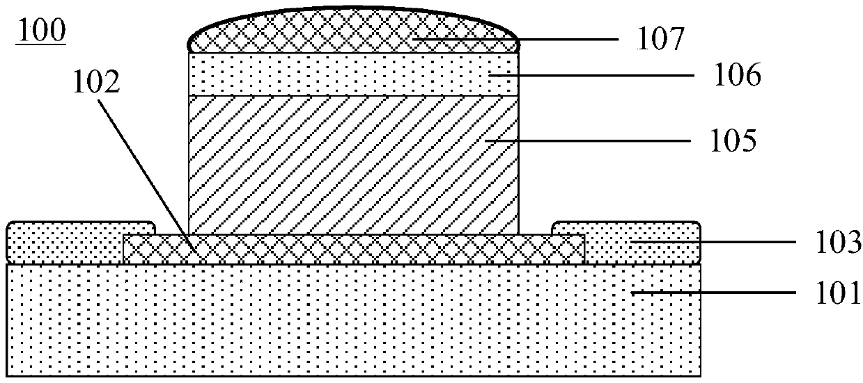
[0007] The purpose of the present invention is to provide a copper pillar bump structure and its manufacturing method, which can overcome the problem of abnormal quality of bump bonding caused by too much or too little solder amount during flip-chip welding at least to a certain extent.

Method used


Image

  • Copper pillar bump structure and manufacturing method thereof
  • Copper pillar bump structure and manufacturing method thereof
  • Copper pillar bump structure and manufacturing method thereof

Examples


Embodiment Construction

[0036] Example embodiments will now be described more fully with reference to the accompanying drawings. Exemplary embodiments may, however, be embodied in many forms and should not be construed as limited to the examples set forth herein; rather, these examples are provided so that this disclosure will be thorough and complete and will fully convey the concept of the exemplary embodiments communicated to those skilled in the art. The same reference numerals in the drawings denote the same or similar structures, and thus their detailed descriptions will be omitted.

[0037]Although relative terms such as "upper" and "lower" are used in this specification to describe the relative relationship of one component of an icon to another component, these terms are used in this specification only for convenience, for example, according to the description in the accompanying drawings directions for the example described above. It will be appreciated that if the modules of the icon are...


PUM


Abstract

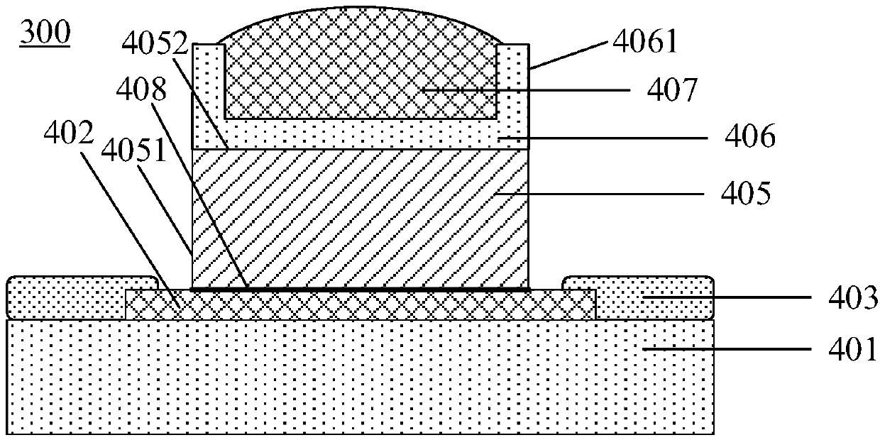
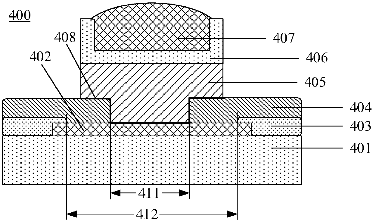
The invention provides a copper pillar bump structure and a manufacturing method thereof, and relates to the technical field of semiconductor production. The structure comprises a semiconductor devicewith a metal bonding pad, a copper pillar arranged on the metal bonding pad, a metal barrier layer with a U-shaped cross section and a solder layer, wherein the middle part of the metal barrier layerlocated on the copper pillar covers the top surface of the copper pillar, the opening of the U-shaped cross section faces the direction away from the copper pillar, and the peripheral part, which islocated on the side edge of the U-shaped cross section, of the metal barrier layer comprises a retaining wall which integrally extends from the middle part of the metal barrier layer and is bent in the direction away from the copper pillar to protrude out of the top surface; and the solder layer is located on the copper pillar and is filled in the U-shaped cross section. According to the technicalscheme provided by the invention, the metal barrier layer with the U-shaped cross section is arranged, and the U-shaped cross section is filled with the solder layer, so that the metal barrier layerwraps the side edge of the solder layer, and the problem of non-wetting caused by insufficient tin amount during tin climbing or the problem of soldering tin bridging caused by too much soldering tincan be solved.

Description

technical field [0001] The invention relates to the technical field of semiconductor production, in particular to a copper pillar bump structure and a manufacturing method thereof. Background technique [0002] With the increasingly powerful functions of integrated circuits, higher performance and higher integration, and the emergence of new integrated circuits, packaging technology plays an increasingly important role in integrated circuit products, and in the value of the entire electronic system The proportion is increasing. At the same time, as the feature size of integrated circuits reaches the nanometer level, transistors are developing towards higher density and higher clock frequency, and packaging is also developing towards higher density. As packaging density continues to increase, chip-to-chip or chip-to-package substrate narrow-pitch electrical interconnections and their reliability have become a challenge. Traditional lead-free solder bump technology has been ...

Claims


Application Information

Patent Timeline
Patent Type & Authority Applications(China)
IPC IPC(8): H01L23/498H01L23/538H01L21/48H01L21/768
CPCH01L21/4853H01L21/76895H01L23/49816H01L23/49838H01L23/5386H01L2224/11
Inventor 不公告发明人
Owner CHANGXIN MEMORY TECH INC
Learn More