Supercharge Your Innovation With Domain-Expert AI Agents!

Electrode assembly

An electrode assembly and positive electrode technology, which is applied in the field of electrode assemblies, can solve the problems of increased internal resistance, accelerated electrode deterioration, thickness difference, etc., and achieves the effect of solving the increased internal resistance and electrode deterioration.

Active Publication Date: 2020-06-02
LG ENERGY SOLUTION LTD
View PDF7 Cites 1 Cited by
  • Summary
  • Abstract
  • Description
  • Claims
  • Application Information

AI Technical Summary

Problems solved by technology

[0009] However, in the manner in which the single cells 4 are fixed using the strap 5 as described above, the ends of the strap 5 are additionally protruded from the uppermost and lowermost layers, thereby causing a difference in thickness.
In addition, when the tape 5 is attached, there is a problem that a part of the edge of the negative electrode 2 (which is cut relatively larger than the positive electrode for stability) is folded
[0010] As mentioned above, due to the thickness difference and folding of the negative electrode, the internal resistance will increase, thereby accelerating the deterioration of the electrode

Method used


Image

  • Electrode assembly
  • Electrode assembly
  • Electrode assembly

Examples


Embodiment approach 1

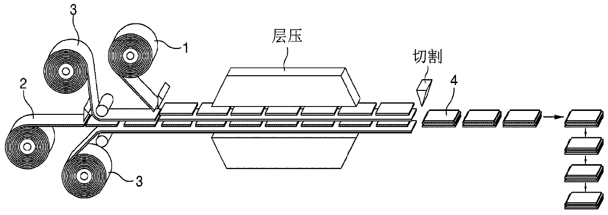
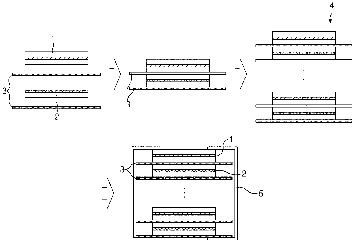
[0070] Figure 3a is a side view illustrating a state in which a plurality of single cells 100 and 101 are laminated according to Embodiment 1, in which figure 2 The single cells 100 are laminated at the uppermost layer, and the diaphragm extension 31 of the uppermost single cell 100 surrounds the entire single cells 100 and 101, and Figure 3b It is a plan view when the state of FIG. 3 is viewed downward from the upper side. Such as Figure 3a and Figure 3b As exemplified in , the electrode assembly according to Embodiment Mode 1 of the present invention is manufactured by laminating a plurality of single cells 100 and 101 . In the remaining single cells 101 except the uppermost single cell 100, the positive electrode 10, the separator 30, the negative electrode 20, and the separator 30 are sequentially laminated from the upper side downward, and each of the contact surfaces to be bonded to each other may be provided. Apply heat and / or pressure. However, the single cel...

Embodiment approach 2

[0078] In the electrode assembly, it is preferable not to provide double-sided positive electrodes in the outermost layer in order to minimize precipitation of lithium (Li) contained in the positive electrode active material. In more detail, a single-sided positive electrode or negative electrode may be provided on the outermost layer to prevent the positive electrode active material from being exposed from the outermost layer. Therefore, in the present invention, as Embodiment 2, a configuration in which a one-sided positive electrode is provided at the outermost layer is provided, and as Embodiment 3, a configuration in which the negative electrode 20 is provided at the outermost layer is provided.

[0079] That is, like the electrode assembly according to Embodiment 1, in the electrode assembly according to Embodiment 2, the single cell 100 including the separator 30 on which the expanded portion 31 is formed is laminated on the uppermost layer, and the positive electrode 10...

Embodiment approach 3

[0081] In the electrode assembly according to Embodiment 3 of the present invention, the negative electrode 20 is additionally laminated in the electrode assembly according to Embodiment 1 so that the negative electrode 20 is disposed on the uppermost layer.

[0082] which is, Figure 3c is a side view illustrating a state in which a plurality of single cells 100 and 101 are laminated according to Embodiment 3 of the present invention, wherein figure 2 The single cells 100 of 2 are laminated at the uppermost layer, and the separator extension 31 of the uppermost single cell 100 surrounds the entire cells 100 and 101 , and then the negative electrode 20 is additionally laminated on the separator extension. As illustrated in the drawing, the electrode assembly according to Embodiment 3 has a structure in which the end of the expanded portion 31 of the separator 30 surrounds and covers the entire uppermost positive electrode 10 in the structure according to Embodiment 1. Referri...


PUM


Abstract

The present invention provides an electrode assembly in which are repeatedly stacked: a negative electrode, which has a negative electrode active material applied on the surface of a negative electrode current collector; a separator; and a positive electrode which has a positive electrode active material applied on the surface of a positive electrode current collector. The electrode assembly comprises monocells having stacked therein a positive electrode, a separator, a negative electrode, and a separator, two or more monocells being stacked on one-another. Any one of the monocells has an extension portion extending lengthwise from one side on the separator. The extension portion of the separator surrounds the monocells stacked on the outermost layer and thus the stacked monocells are fixed. In addition, the present invention additionally provides an electrode assembly in which are repeatedly stacked: a negative electrode, which has a negative electrode active material applied on the surface of a negative electrode current collector; a separator; and a positive electrode which has a positive electrode active material applied on the surface of a positive electrode current collector.The electrode assembly comprises monocells having stacked therein a positive electrode, a separator, a negative electrode and a separator, two or more monocells being stacked on one-another. Two or more of the monocells respectively have a positive electrode extension portion which is the positive electrode current collector extending lengthwise from one side and a negative electrode extension portion which is the negative electrode current collector extending lengthwise from the other side. The positive electrode extension portion and the negative electrode extension portion are attached toa positive electrode extension portion and a negative electrode extension portion of another monocell, respectively, and thus the stacked monocells are fixed.

Description

technical field [0001] This application claims the benefit of priority from Korean Patent Application No. 10-2018-0112395 filed on September 19, 2018, the entire contents of which are hereby incorporated by reference. [0002] The present invention relates to an electrode assembly embedded in a secondary battery, and more particularly, to an electrode assembly fixed by an extension extending from a separator or an extension extending from a collector Problems arising in electrode assemblies using tapes for fixation after lamination and stacking. Background technique [0003] Unlike primary batteries, secondary batteries are rechargeable, and also have a high possibility of being compact in size and high in capacity. Therefore, recently, many studies on rechargeable batteries are being conducted. As technology develops and demands on mobile devices increase, the demand for rechargeable batteries as an energy source is rapidly increasing. [0004] Such a secondary battery i...

Claims


Application Information

Patent Timeline
Patent Type & Authority Applications(China)
IPC IPC(8): H01M10/04H01M10/0583H01M2/02H01M50/105
CPCH01M10/0413H01M10/0585H01M10/052H01M50/46H01M50/105H01M50/211H01M10/0583Y02E60/10H01M10/0525H01M10/0459Y02P70/50H01M10/0436H01M50/116H01M50/461H01M50/538H01M10/0468
Inventor 金容俊郑熙锡成耆元李恩周
Owner LG ENERGY SOLUTION LTD
Features
  • R&D
  • Intellectual Property
  • Life Sciences
  • Materials
  • Tech Scout
  • Unparalleled Data Quality
  • Higher Quality Content
  • 60% Fewer Hallucinations
Learn More