
Variable pitch impeller and wind driven generator

A blade and pitch technology, applied in wind turbines, wind turbine combinations, wind turbines in the same direction as the wind, etc., can solve problems such as low efficiency, large blade resistance, and inconvenient transportation, and achieve improved efficiency, The effect of reducing drag

Pending Publication Date: 2020-06-05
季文斌
View PDF0 Cites 1 Cited by
  • Summary
  • Abstract
  • Description
  • Claims
  • Application Information

AI Technical Summary

Problems solved by technology

[0003] Regardless of the horizontal axis wind turbine or the vertical axis wind turbine, there are some disadvantages. For example, the tower column of the horizontal axis wind turbine is generally 30-40 meters high, and the outer diameter of the blade is as long as 30 meters. The strength of the blade is extremely demanding. High, and the cost is very high, the transportation is inconvenient, and the installation and maintenance are very difficult
Although the vertical axis wind turbine is small in size, it is more convenient to install and transport, but the blades of the traditional vertical axis wind turbine have large resistance when they rotate, and the efficiency of converting wind energy kinetic energy into electrical energy is not high

Method used


Image

  • Variable pitch impeller and wind driven generator
  • Variable pitch impeller and wind driven generator
  • Variable pitch impeller and wind driven generator

Examples


Embodiment 1

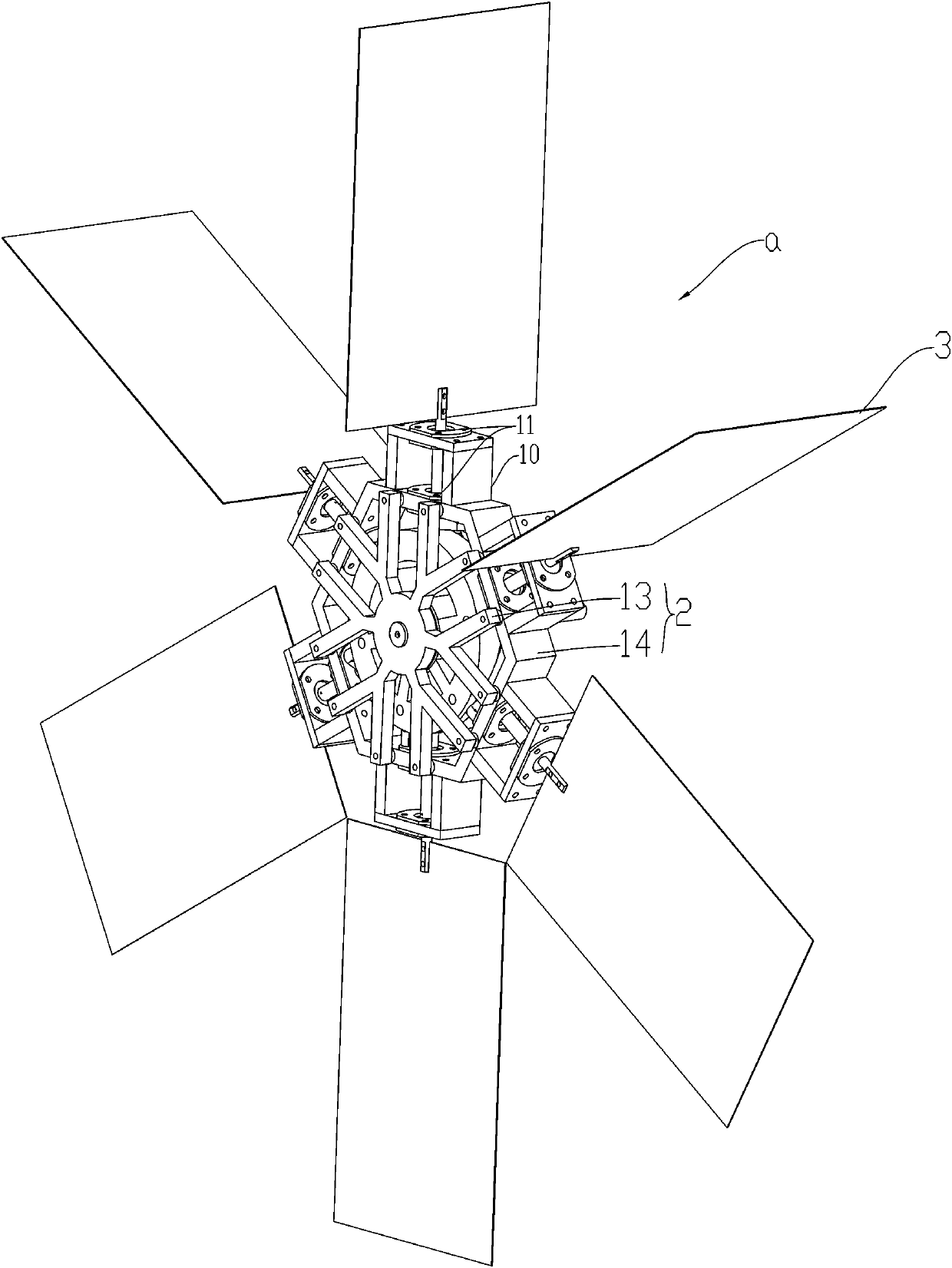
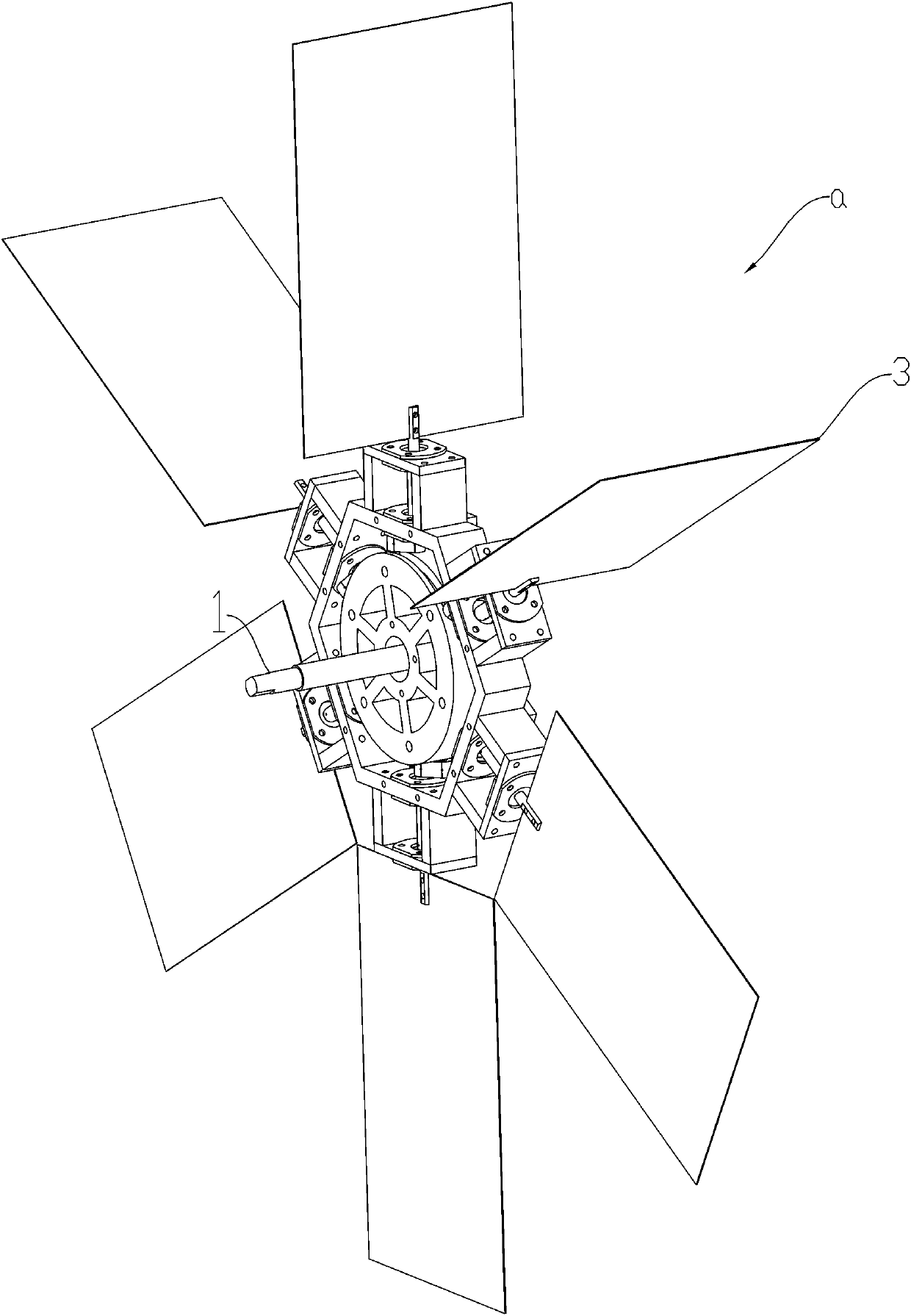
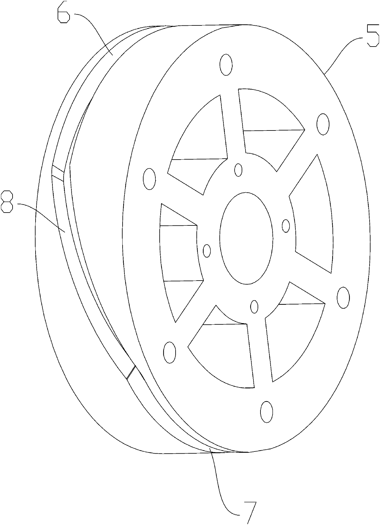
[0023] Such as Figure 1 to Figure 7 As shown, the pitch impeller of the present invention includes a main shaft 1 , a wheel frame 2 fixed at one end of the main shaft 1 , and a group of blades 3 distributed around the wheel frame 2 . The synchronous rotation of the paddle 3 and the wheel frame 2 drives the rotation of the main shaft 1 . There is a rotatable connection between the paddle 3 and the wheel frame 2 . A pitch-changing mechanism 4 is provided between the main shaft 1 and the wheel frame 2 . When the blade 3 rolls above the center line o of the wheel frame 2, the direction of the blade 3 above the center line o is changed by the pitch-changing mechanism 4, so that the blade 3 and the wheel Frame 2 is vertical, forms the windward side. When the paddle 3 rolls below the center line a of the wheel frame 2, the pitch change mechanism 4 changes the direction of the paddle 3 below the center line o, so that the paddle 3 and the wheel rack 2 parallel.

[0024] Preferab...

Embodiment 2

[0030] Such as Figure 8 As shown, the wind power generator of the present invention includes a column 15, and the pitch-changing impeller a described in Embodiment 1 is arranged symmetrically on both sides of the column 15, and the cylindrical cam 5 of the pitch-changing impeller a passes through a set of mounting columns 17 is fixedly connected with the column 15. The other end of the main shaft 1 is connected with a pulley 16 . The rotor of the generator set is driven to rotate by the pulley 16 to generate electricity.


PUM


Abstract

The invention discloses a variable pitch impeller with small blade rotation resistance and a wind driven generator. According to the adopted technical scheme, the impeller comprises a main shaft, a wheel carrier fixed at one end of the main shaft, and a group of blades distributed on the wheel carrier in a surrounding mode; and the impeller is characterized in that the blades are rotatably connected with the wheel carrier, a variable pitch mechanism is arranged between the main shaft and the wheel carrier, when the blades roll to the position above the center line of the wheel carrier, the blades are perpendicular to the wheel carrier through the variable pitch mechanism, and when the blades roll to the position below the center line of the wheel carrier, the blades are parallel to the wheel carrier through the variable pitch mechanism.

Description

technical field [0001] The invention relates to a variable pitch impeller and a wind power generator. Background technique [0002] The types of wind turbines mainly include horizontal axis wind turbines and vertical axis wind turbines. Among them, horizontal axis wind turbines are divided into two types: lift type and drag type. The lift-type wind turbine rotates at a fast speed, and the drag-type wind turbine rotates at a slow speed. For wind power generation, lift-type horizontal axis wind turbines are mostly used. Most horizontal-axis wind turbines have a wind-facing device that rotates as the wind changes direction. For small wind-driven generators, the wind-facing device uses a tail rudder, while for large-scale wind-driven generators, a transmission mechanism composed of wind direction sensing elements and servo motors is used. The vertical-axis wind turbine does not need to face the wind when the wind direction changes, which is a big advantage over the horizonta...

Claims


Application Information

Patent Timeline
IPC IPC(8): F03D7/02F03D1/06F03D1/02F03D9/25B63H1/06
CPCB63H1/06F03D1/02F03D1/065F03D7/022F03D9/25Y02E10/72
Inventor 季文斌
Owner 季文斌
Learn More