Supercharge Your Innovation With Domain-Expert AI Agents!

Clamp assembly for cable processing device and cable processing device

A component and fixture technology, applied in the direction of electrical components, cable/conductor manufacturing, circuits, etc., can solve the problems of complex structure and heavy fixture components.

Pending Publication Date: 2020-06-26
KOMAX HOLDING
View PDF7 Cites 0 Cited by
  • Summary
  • Abstract
  • Description
  • Claims
  • Application Information

AI Technical Summary

Problems solved by technology

[0006] However, this structure is complex and, moreover, the piston rod and cylinder make the clamp assembly heavy and thus increase, for example, the weight that needs to be moved during twisting of the cable end.

Method used


Image

  • Clamp assembly for cable processing device and cable processing device
  • Clamp assembly for cable processing device and cable processing device
  • Clamp assembly for cable processing device and cable processing device

Examples


Embodiment Construction

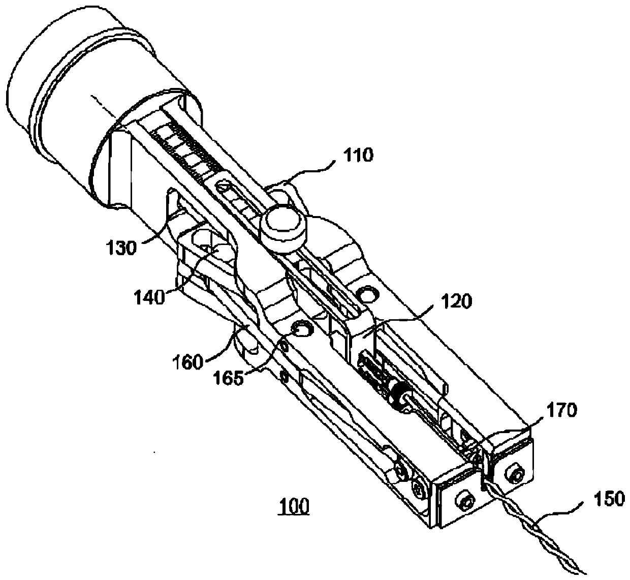
[0025] figure 1 A schematic perspective view of a prior art cable clamp 100 is shown. exist figure 1 Among them, the cable clamp 100 includes a pair of jaws 170 for clamping ends of a pair of cables 150 inserted into a region between the jaws 170 . The limit stopper 120 ensures an appropriate length of insertion of the pair of cables 150 in the axial direction. The slider 110 is arranged on the piston rod 130 of the cable clamp 100 . The piston rod 130 is part of a pneumatically operated cylinder and is substantially movable back and forth along the common axis of the cable 150 and the cable clamp 100 .

[0026] Bolts 140 on either side of slider 110 engage corresponding slots in each of a pair of levers 160 . As the piston rods 130 move, each control rod 160 pivots in a substantially synchronous manner about a rotational axis 165 such that the jaws 170 grip the pair of cables 150 substantially at a central position.

[0027] The mechanical complexity of the bolt 140, sli...


PUM


Abstract

The invention relates to a clamp assembly for a cable processing device and the cable processing device. The clamp assembly includes a pair of clamping pistons. The clamp pistons are configured to selectively hold at least one cable inserted into a piston intermediate portion located at a fixed position relative to the clamp piston. Each clamping piston is partially accommodated in the pneumatic cylinder. Each pneumatic cylinder comprises an air cylinder chamber for containing air, and the air pressure of each air cylinder chamber acts on the surface of the corresponding clamping piston. Eachgripping piston is configured to be pneumatically actuated toward the piston intermediate portion when an air pressure of an amount of air of the respective cylinder chamber increases. Each cylinder chamber is in fluid communication with a respective air conduit, the air conduits having substantially the same structure, and the air conduits are in fluid communication with a common air inlet. The clamp assembly is suitable for the cable processing device.

Description

technical field [0001] The present invention relates to a clamp assembly for selectively holding at least one cable in a cable processing device. Background technique [0002] In conventional cable processing devices, especially in cable processing devices for twisting pre-assembled cable bundles of eg two cables, cable clamps are provided for clamping and twisting the cable bundles relative to each other. For example, such a conventional device is provided with a rotating fixture at one end, and a rotating fixture is provided opposite the rotating fixture. Each clamp in such conventional arrangements may include an adjustable limit stop to facilitate manual insertion of the corresponding cable end of the cable bundle. An example of such a conventional cable processing device is disclosed, for example, in DE 20 2010 001 324 U. [0003] Conventional cable clamps include a pair of jaws. In order to grip the inserted cable end or ends, the jaws are moved towards the gripping...

Claims


Application Information

Patent Timeline
IPC IPC(8): H01B13/02
CPCH01B13/0207
Inventor 拉斐尔·塞恩
Owner KOMAX HOLDING
Features
  • R&D
  • Intellectual Property
  • Life Sciences
  • Materials
  • Tech Scout
  • Unparalleled Data Quality
  • Higher Quality Content
  • 60% Fewer Hallucinations
Learn More