Supercharge Your Innovation With Domain-Expert AI Agents!

Active aero system in-mold assembly hinge modular frame

A technology of in-mold assembly and modularization, which is applied in the direction of cooling combination layout of the power unit, component optimization, power unit, etc., can solve the problem of additional floor space and other issues

Active Publication Date: 2020-06-30
MAGNA EXTERIORS INC
View PDF21 Cites 0 Cited by
  • Summary
  • Abstract
  • Description
  • Claims
  • Application Information

AI Technical Summary

Problems solved by technology

These parts are molded and assembled, which requires additional equipment, floor space, and labor, and may include more assembly variations

Method used


Image

  • Active aero system in-mold assembly hinge modular frame
  • Active aero system in-mold assembly hinge modular frame
  • Active aero system in-mold assembly hinge modular frame

Examples


Embodiment Construction

[0022] The following description of the preferred embodiments is merely exemplary in nature, and is not intended to limit the present invention, the application or use of the present invention.

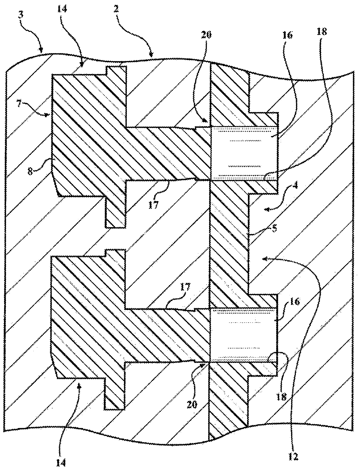
[0023] Referring generally to the drawings, an in-mold assembly of an active pneumatic hinge modular frame is provided, which allows the joining of multiple components assembled directly from the molding process tool. These components include, for example, blade end pivots, blade end stops, drive links, and / or frame end stops. The geometric factors in the in-mold assembly (IMA) design contribute to the final assembly of the system, which is preferably the actuator that drives the blade interface.

[0024] Geometric factors allow components (eg, blade end pivots, blade end stops, drive links, frame end stops, etc.) to be directly attached from the mold and assembled into a single part. These components provide various functions in the complete system, including rotary engagement and torque...


PUM


Abstract

A manufacturing process for an active grille shutter arrangement includes in-mold assembly of an active aero hinge modular frame that allows for the joining of multiple components that are to be assembled directly out of the molding process tooling. These components could be the vane end pivots, vane end stops, drive linkages, frame end stops, etc. Final assembly of the system is facilitated by geometrical considerations and molding material considerations in the in-mold assembly (IMA) design.

Description

[0001] Cross references to related applications [0002] This application is a PCT international patent application that claims the priority of U.S. Provisional Application No. 62 / 570,391 filed on October 10, 2017. The disclosure of the aforementioned application is incorporated herein by reference. Technical field [0003] The invention relates to an in-mold process for manufacturing two-piece connected and movable parts. Background technique [0004] Attempts have been made to optimize the cooling of various auto parts. Some of the various devices have been developed. These devices have been designed to control the airflow in the entire car engine compartment to transfer the desired heat from the engine, transmission, and other heat-generating components to maintain optimum Working temperature. [0005] It is also expected that the engine will reach normal operating temperature as soon as possible after the engine is started. When the temperature of the engine is basically the s...

Claims


Application Information

Patent Timeline
Patent Type & Authority Applications(China)
IPC IPC(8): B29C45/14
CPCB29C45/0017B29C2045/1601B29C2045/1659B29C2045/0065B29C2045/0068B29C45/0081B29C45/06B29L2031/22B29L2031/3055B29L2031/779B29C45/006B60K11/085Y02T10/88B29C45/14336
Inventor 布伦东·林德伯格罗斯·J·帕尔帕特安东尼·J·波维内利
Owner MAGNA EXTERIORS INC
Features
  • R&D
  • Intellectual Property
  • Life Sciences
  • Materials
  • Tech Scout
  • Unparalleled Data Quality
  • Higher Quality Content
  • 60% Fewer Hallucinations
Learn More