Supercharge Your Innovation With Domain-Expert AI Agents!

Solid state light sources enabling digital spokes when used with a color wheel

A solid-state light source and light source technology, which is applied to the parts, optics, and optical components of color TVs, and can solve the problems of reducing the brightness of the illumination system and constantly changing

Pending Publication Date: 2020-06-30
SIGNIFY HLDG BV
View PDF22 Cites 0 Cited by
  • Summary
  • Abstract
  • Description
  • Claims
  • Application Information

AI Technical Summary

Problems solved by technology

[0003] A disadvantage of using a color wheel with multiple color segments is that the color of the light emitted by known illumination systems is constantly changing during the so-called spoke time
However, cutting off the light during the spoke time reduces the brightness of the illumination system, which is highly undesirable for a projection setup

Method used


Image

  • Solid state light sources enabling digital spokes when used with a color wheel
  • Solid state light sources enabling digital spokes when used with a color wheel
  • Solid state light sources enabling digital spokes when used with a color wheel

Examples


Embodiment Construction

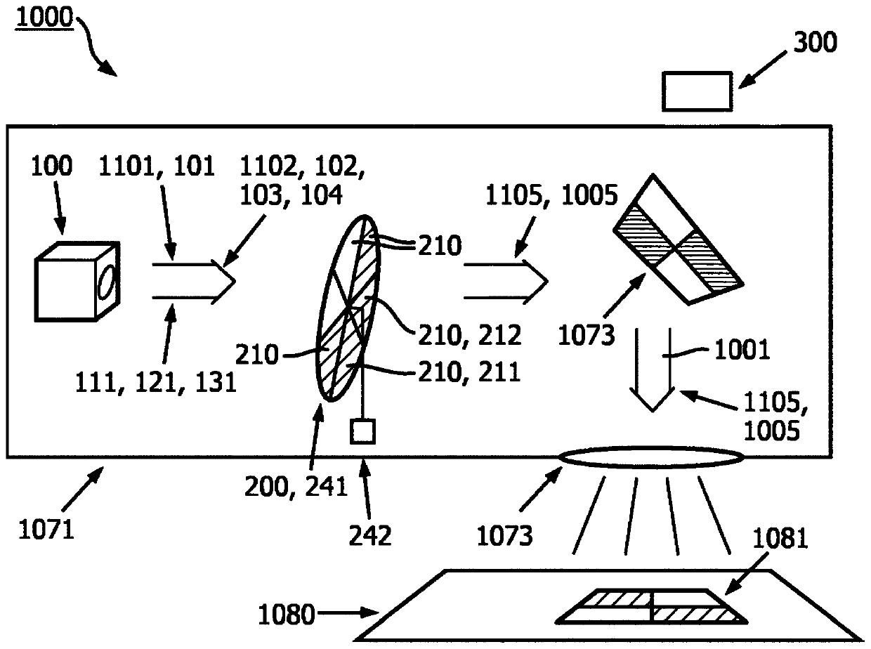
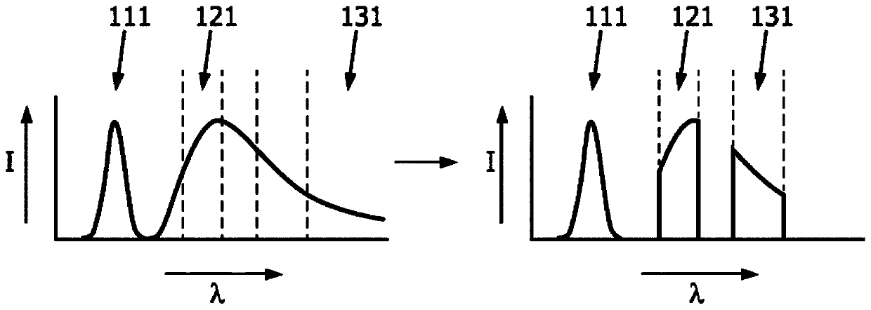
[0120] figure 1 An embodiment of a system 1000 for processing light is shown schematically. System 1000 is configured to provide beam 1005 of system light 1001 along main beam path 1105 . System light 1001 includes one or more of: first light 111 with a first spectral distribution, second light 121 with a second spectral distribution, and third light 131 with a third spectral distribution. The first, second and third spectral distributions are different from each other; see also Figure 2a.

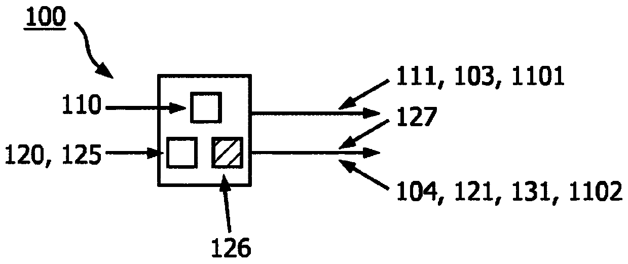
[0121] System 1000 includes lighting arrangement 100 , optical filter system 200 and control system 300 .

[0122] The lighting arrangement 100 may be configured to provide a first light beam 101 along a first light beam path 1101, the first light beam 101 comprising primary light 103 having a spectral power distribution in which for example at least 80% of the spectral power is provided by the first light 111, one of the second light 121 and the third light 131. Furthermore, the light...


PUM


Abstract

The invention provides a system (1000) for processing light, the system (1000) configured to provide along a main beam path (1105) a beam (1005) of system light (1001), wherein the system light (1001)comprises one or more of first light (111) having a first spectral distribution, second light (121) having a second spectral distribution, and third light (131) having a third spectral distribution,wherein the first, second, and third spectral distributions mutually differ, wherein the system (1000) comprises: a lighting arrangement (100) configured to provide along a first beam path (1101) a first beam (101) comprising primary light (103) having a spectral power distribution with at least 80% of the spectral power consisting of one of the first light (111), the second light (121), and the third light (131), and / or configured to provide along a second beam pat (1102) a second beam (102) comprising composed light (104) having a spectral distribution with at least 80% of the spectral powerconsisting of the two others of the first light (111), the second light (121), and the third light (131); an optical filter system (200) comprising a plurality of segments (210), wherein two or moresegments (210) have different transmission characteristics for one or more of the primary light (103) and the composed light (104); wherein during operation of the system (1000) the optical filter system (200) is configured to have the segments (210) of the plurality of segments (210) sequentially intercept the main beam path (1105) or the second beam path (1102), wherein during a time period (tsp) the beam path (1105, 1102) is partially intercepted by a first segment (211) and partially intercepted by a second segment (212); a control system (300) configured to control the lighting arrangement (100) and the optical filter system (200) such that during at least part of the time period (tsp) at least 80% of a spectral power distribution of the system light (1001) of the beam (1005) of system light (1001) consists of the primary light (103).

Description

technical field [0001] The invention relates to a system for processing light and a method for processing light (with such a system). The invention also relates to a computer program product, eg for carrying out such a method. Furthermore, the invention relates to a projection system or a luminaire comprising a system (for processing light). Background technique [0002] Illumination systems for projection devices are known per se. They are used inter alia in projection devices such as beamers and projection televisions. In such image projection systems, light generated in an illumination system impinges on an image creation unit such as a liquid crystal display (also denoted LCD) or such as a digital light processing unit (also denoted DLP) or such as a liquid crystal on silicon (also denoted for LCoS)), after which the image is projected onto a screen or wall. Illumination systems for projection devices typically emit light in a series of colors of light that repeat ov...

Claims


Application Information

Patent Timeline
Patent Type & Authority Applications(China)
IPC IPC(8): H04N9/31G02B26/00G03B21/20
CPCG02B26/008G03B21/204G03B33/08H04N9/3117H04N9/3158H04N9/3164H04N9/3182G03B21/206
Inventor V·范布洛克霍文R·库尔B·A·T·迪尔斯J-J·P·J·范登伯格
Owner SIGNIFY HLDG BV
Features
  • R&D
  • Intellectual Property
  • Life Sciences
  • Materials
  • Tech Scout
  • Unparalleled Data Quality
  • Higher Quality Content
  • 60% Fewer Hallucinations
Learn More