Heat management module of engine cooling system and engine cooling system

A technology for engine cooling and thermal management, which is applied in the direction of engine cooling, engine components, machines/engines, etc. It can solve problems such as poor combustion conditions, reduced heat dissipation, and reduced service life of parts, so as to reduce processing costs and processing difficulties , reduce temperature fluctuations, reduce the effect of cold and heat shock

Inactive Publication Date: 2020-07-03
CHONGQING CHANGAN AUTOMOBILE CO LTD
View PDF8 Cites 2 Cited by
  • Summary
  • Abstract
  • Description
  • Claims
  • Application Information

AI Technical Summary

Problems solved by technology

[0003] 1. The traditional cooling system has a simple structure and cannot meet the diverse needs of customers
For example, the HVAC 7 waterway is always open, and the cold water in the waterway participates in the circulation during the cold start and warm-up stages, resulting in slow temperature rise and slow warm-up speed of the engine body in winter low-temperature environments, resulting in poor combustion conditions and customers waiting for the air conditioner to heat up Long wait; when the temperature is high in summer, the branch diverts the flow of antifreeze, which reduces the flow of the radiator 8 and reduces the heat dissipation. At this time, there is a risk of high water temperature. At the same time, in order to reduce the risk, sufficient water pump performance will be left in the design of water pump 1 margin, which causes waste of power
[0004] 2. Due to the

Method used


Image

  • Heat management module of engine cooling system and engine cooling system
  • Heat management module of engine cooling system and engine cooling system
  • Heat management module of engine cooling system and engine cooling system

Examples


Example Embodiment

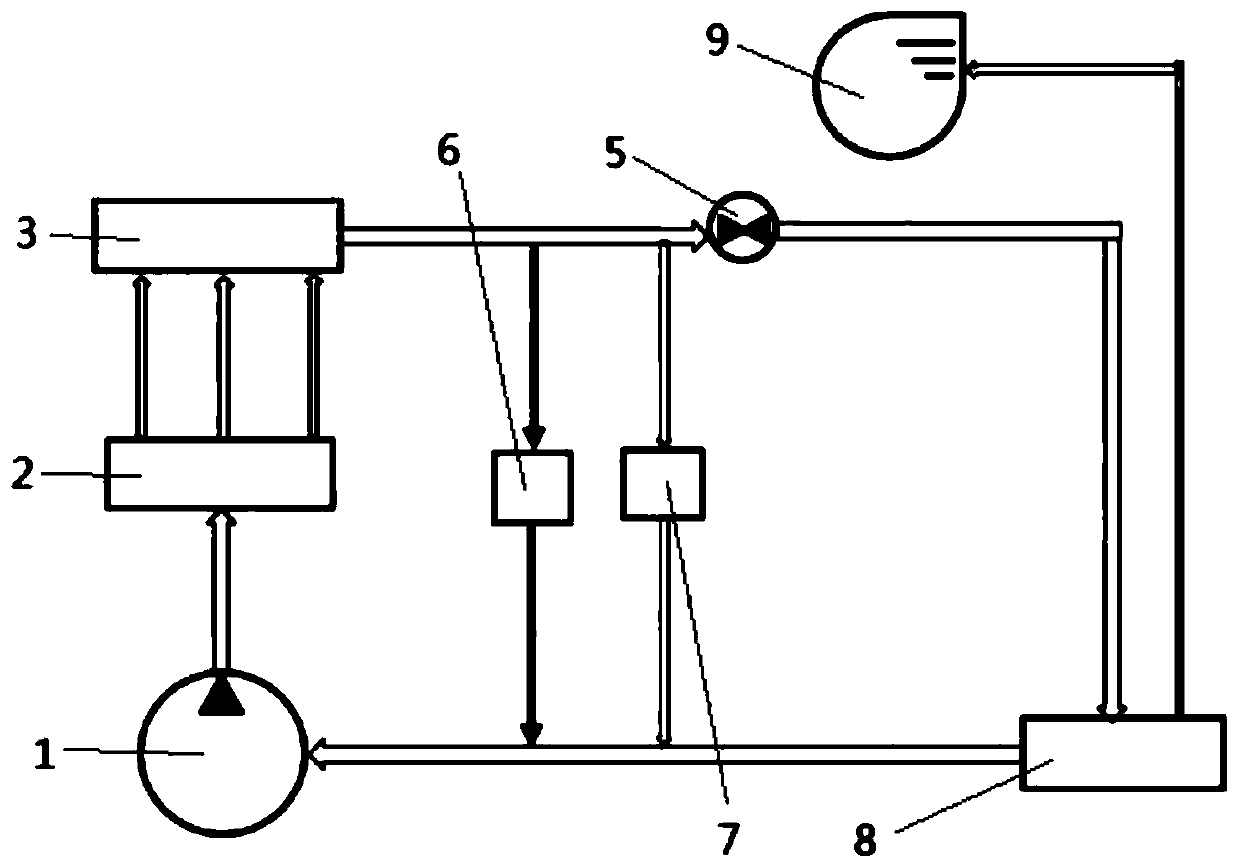
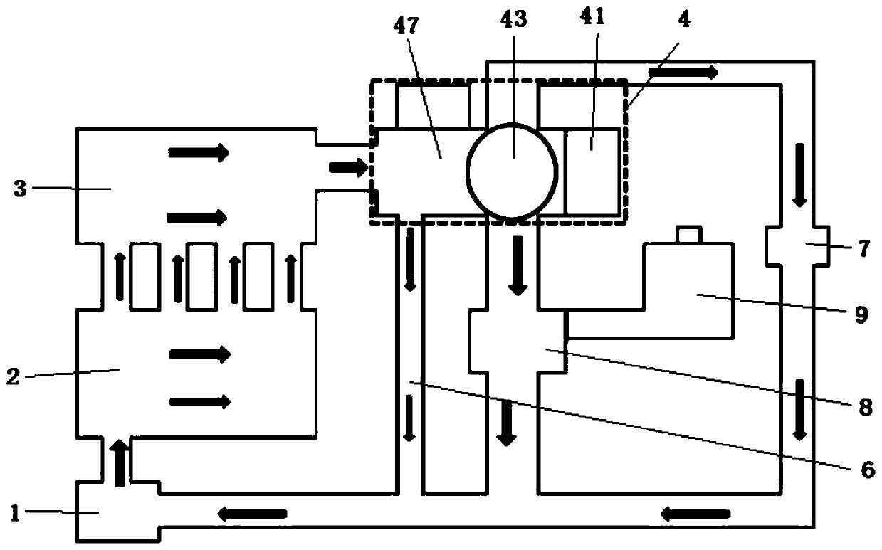
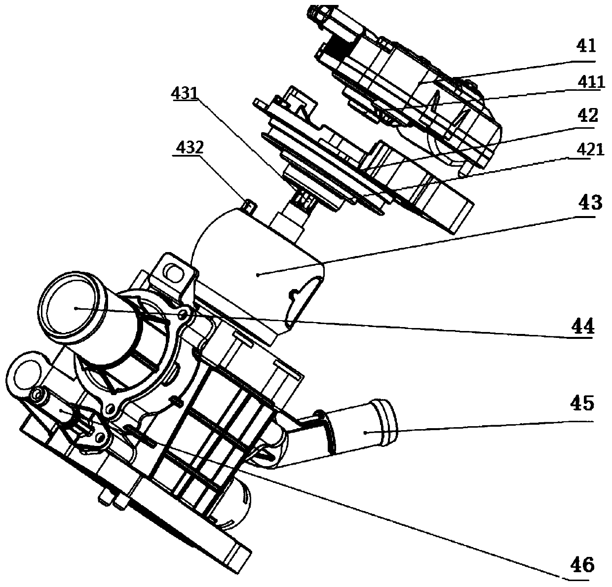
[0024] Such as Figure 2-Figure 6 As shown, the engine cooling system thermal management module 4 in this embodiment includes a housing, an actuator 41, and a ball valve 43. The actuator 41 is installed on the housing, and the ball valve 43 is installed in the housing and is connected to the housing. The output shaft of the actuator 41 is in transmission connection, and the housing is provided with a housing water inlet for communicating with the water outlet of the engine cylinder head water jacket 3, an HVAC pipe 45 for communicating with the HVAC 7, and a In the radiator pipe 44 communicating with the radiator 8, the ball valve 43 includes a spherical valve core, and the spherical valve core is provided with a water inlet that is connected to the water inlet of the housing for connecting to the HVAC pipe 45 The docking heating valve port 433 and the radiator valve port 434 for docking with the radiator pipe 44; the actuator 41 can drive the ball valve 43 to rotate, thereby ch...


PUM


Abstract

The invention discloses a heat management module of an engine cooling system and the engine cooling system. The heat management module of the engine cooling system comprises a shell, an actuator and aball valve. The actuator is electrically connected with the electronic control unit of an engine. The electronic control unit of the engine can control the actuator to drive the ball valve to rotate,so that the butt joint area between a heating and ventilating valve opening and a heating and ventilating pipe and the butt joint area between a radiator valve opening and a radiator pipe can be changed, and then the flow of anti-freezing liquid of a heating and ventilating water channel and a radiator water channel is changed. The engine cooling system comprises the anti-freezing liquid, a waterpump, a cylinder body water jacket, a cylinder cover water jacket, a heating and ventilating device, the radiator and the heat management module of the engine cooling system. Under the action of thewater pump, the anti-freezing liquid sequentially flows to the cylinder body water jacket, the cylinder cover water jacket and the heat management module of the engine cooling system, then flows to aminor-cycle rubber pipe, the heating and ventilating device and the radiator and finally flows back to the water pump.

Description

technical field [0001] The invention relates to the technical field of automobile engine cooling systems, in particular to an engine cooling system thermal management module and an engine cooling system. Background technique [0002] The traditional engine cooling system can only adjust the antifreeze flow and water temperature in a rough and large range. The performance margin will be large, which will cause a waste of power and cause the engine body to heat up slowly. During cold start, due to the low temperature of the intake system and the cylinder, it is difficult for the gasoline to be completely atomized, resulting in incomplete combustion, increased hydrocarbon emissions, and the problem of increasing the amount of fuel at the same time; in addition, the temperature of the engine oil is low, The friction of the internal moving parts of the engine is high, and the fuel consumption is also high; in this case, it is necessary to increase the temperature of the engine b...

Claims


Application Information

Patent Timeline
IPC IPC(8): F01P7/16F01P3/02F01P7/14
CPCF01P3/02F01P7/165F01P2003/028F01P2007/146
Inventor 翟华磊刘玉琦杨向超张江
Owner CHONGQING CHANGAN AUTOMOBILE CO LTD
Why Eureka
Try Eureka