
Clamp of aero-engine turbine blade shroud thinning part and machining method thereof

A technology of aero-engines and turbine blades, which is applied in air transportation, metal processing equipment, metal processing machinery parts, etc., can solve problems such as unrealizable and difficult, and achieve the effects of reducing costs, improving production efficiency, and ensuring stability

Active Publication Date: 2020-07-28
AECC AERO SCI & TECH CO LTD
View PDF6 Cites 2 Cited by
  • Summary
  • Abstract
  • Description
  • Claims
  • Application Information

AI Technical Summary

Problems solved by technology

The thinned part of the crown is a waist structure with R at the root of the transfer. The waist-shaped blind groove structure of the thinned part of the crown cannot be realized by grinding. The process considers the use of CNC milling, and the design drawing requires shock absorption. The roughness of the groove reaches Ra3.2, and there are vibration marks caused by milling in the scientific research and batch production stages. The depth of the vibration marks is 0.05-0.10mm, which requires 100% manual clamping to remove, which is extremely difficult

Method used


Image

  • Clamp of aero-engine turbine blade shroud thinning part and machining method thereof
  • Clamp of aero-engine turbine blade shroud thinning part and machining method thereof
  • Clamp of aero-engine turbine blade shroud thinning part and machining method thereof

Examples


Embodiment 1

[0041] refer to Figure 1-6 , the present invention provides a technical solution:

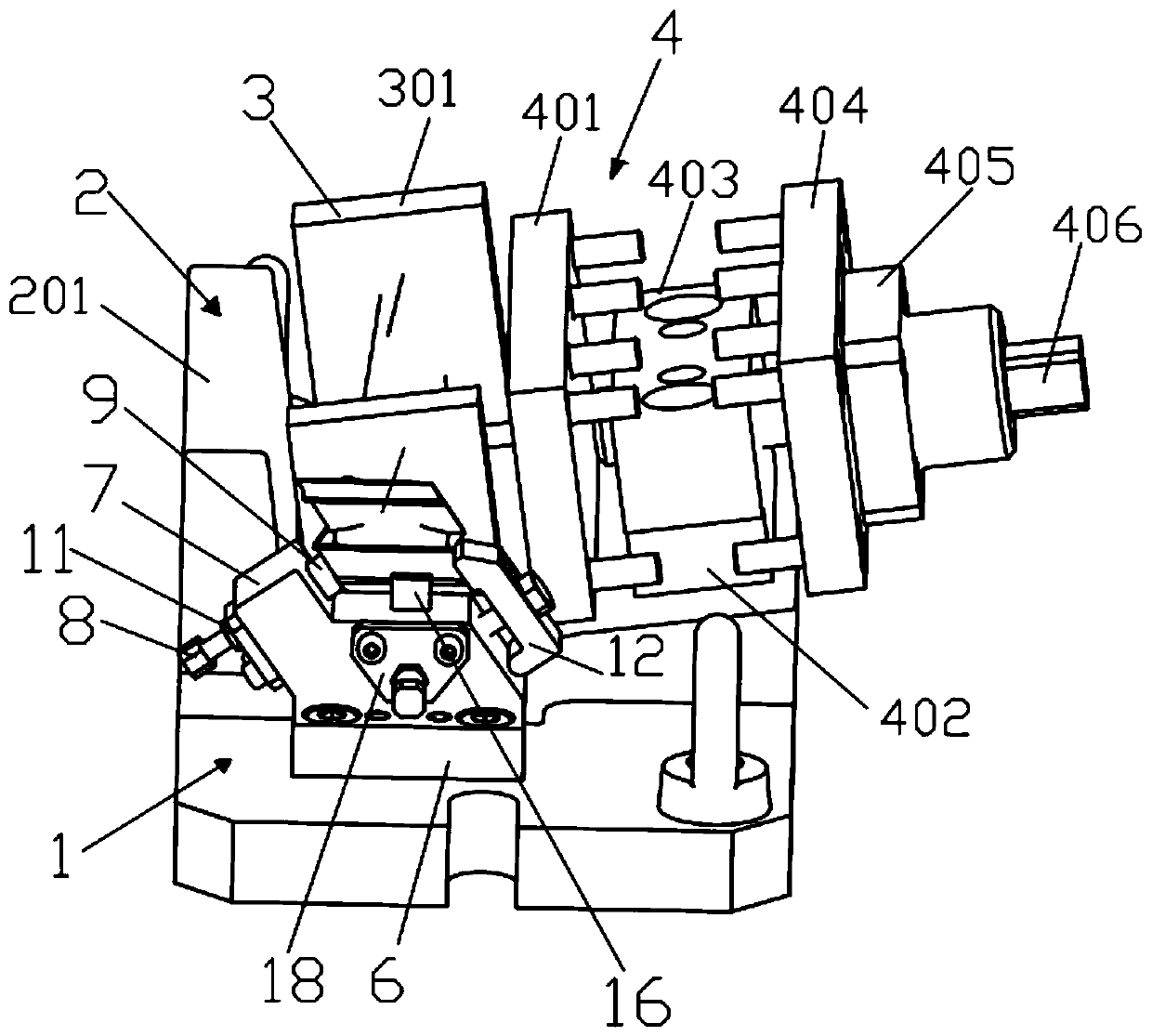
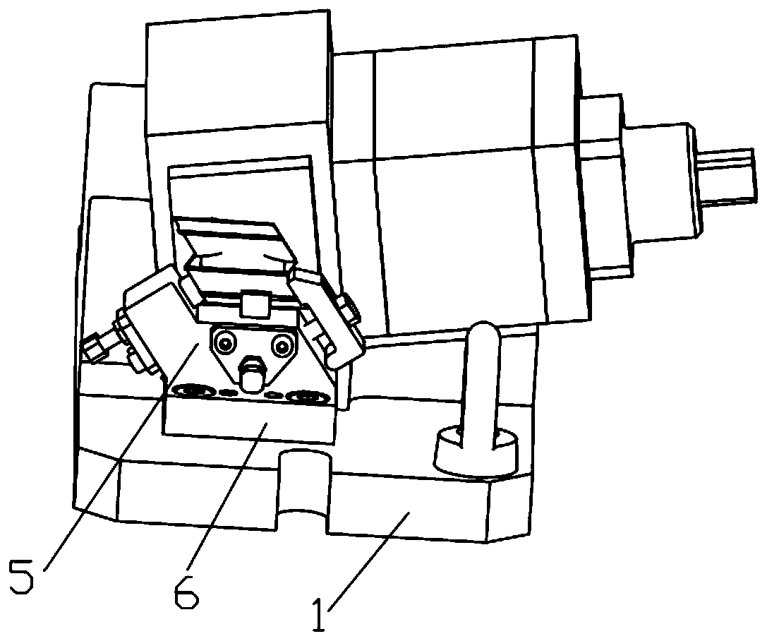
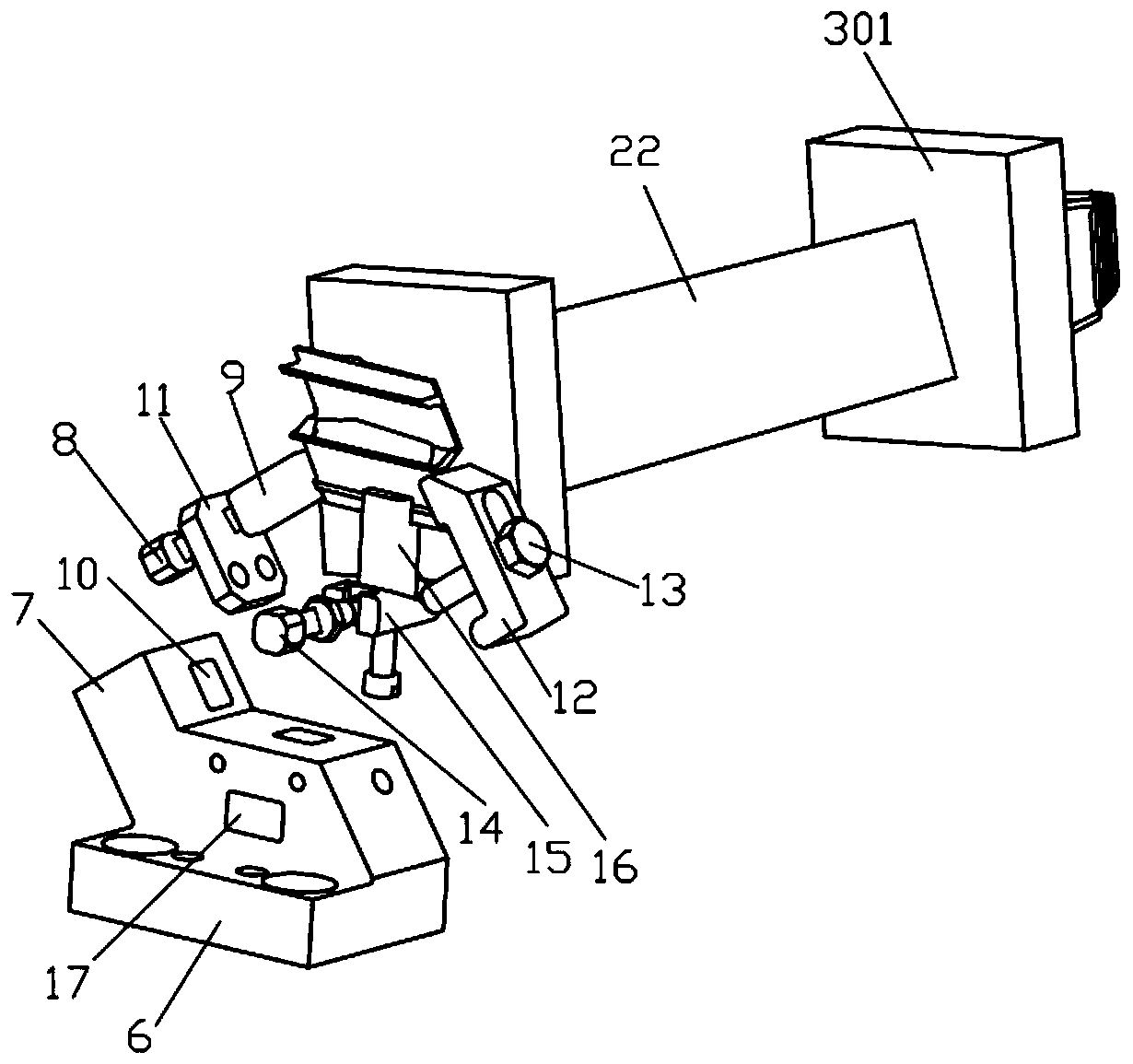
[0042] Please refer to Figure 1-2 , a fixture for the thinning part of the turbine blade shroud of an aeroengine, comprising a base 1, a main positioning assembly 2 of a square box on the airfoil profile, a positioning assembly 3 on the back side of the square box, a positioning assembly 4 on the trailing edge surface of the square box, and a positioning assembly 5 for the shroud The positioning assembly 4 on the rear edge surface of the square box is slidably installed on the base 1 and attached to the square box on the surface of the blade body basin, and the positioning assembly 3 on the back side of the square box is installed on the base 1 and used to fix the The root of the blade, the main positioning assembly 2 of the airfoil profile square box is installed on the base 1 and is located in the square box at the back of the blade airfoil, and the blade crown positioning assembly 5 is in...


PUM


Abstract

The invention discloses a clamp of an aero-engine turbine blade shroud thinning part and a machining method thereof. The clamp comprises a base, a blade body molded surface square box main positioningassembly, a square box back face positioning assembly, a square box rear edge face positioning assembly and a blade shroud part positioning assembly, the square box rear edge face positioning assembly is installed on the base in a sliding mode and attached to a blade body basin face square box, the square box back face positioning assembly is installed on the base and used for fixing a blade root, the blade body molded face square box main positioning assembly is installed on the base and located on the blade body back face square box, and the blade shroud part positioning assembly is mountedon the base through a tail base and is attached to and pressed against the blade shroud part of a blade. The clamp can reduce a tool vibration trace of the blade shroud thinning part, improves the quality of the surface of the blade shroud thinning part, improves the product percent of pass and improves the machining efficiency.

Description

technical field [0001] The invention relates to the technical field of aero-engine blade processing, in particular to a fixture for a thinned part of an aero-engine turbine blade shroud and a processing method thereof. Background technique [0002] Turbine blades are the core parts of the engine. The key indicator of high-performance engines is a large thrust-to-weight ratio. In order to increase the thrust-to-weight ratio of the engine, it is necessary to increase the temperature before the turbine. The temperature before the turbine of the fourth-generation and fifth-generation engines can reach 1800~ 2100K, which puts forward new requirements for the high temperature resistance of the material and the design structure of the turbine blades, but the turbine blades are often made of high-temperature alloy precision casting blanks. [0003] High-temperature alloy precision casting blades have defects such as poor performance during cutting, milling processing is prone to tre...

Claims


Application Information

Patent Timeline
IPC IPC(8): B23C3/18B23Q3/06
CPCB23C3/18B23Q3/063Y02T50/60
Inventor 雷浩强裴聪任凤英周林印灿景明辉王强
Owner AECC AERO SCI & TECH CO LTD
Learn More