Automatic ultrasonic flexible welding system
An ultrasonic welding and welding system technology, applied in welding equipment, non-electric welding equipment, metal processing equipment, etc., can solve the problems of single application variety, low welding efficiency, and large space occupied by production equipment, achieving a high degree of automation and welding process. Precise, cost-saving effect on equipment
- Summary
- Abstract
- Description
- Claims
- Application Information
AI Technical Summary
Problems solved by technology
Method used
Image


Examples
Embodiment 1
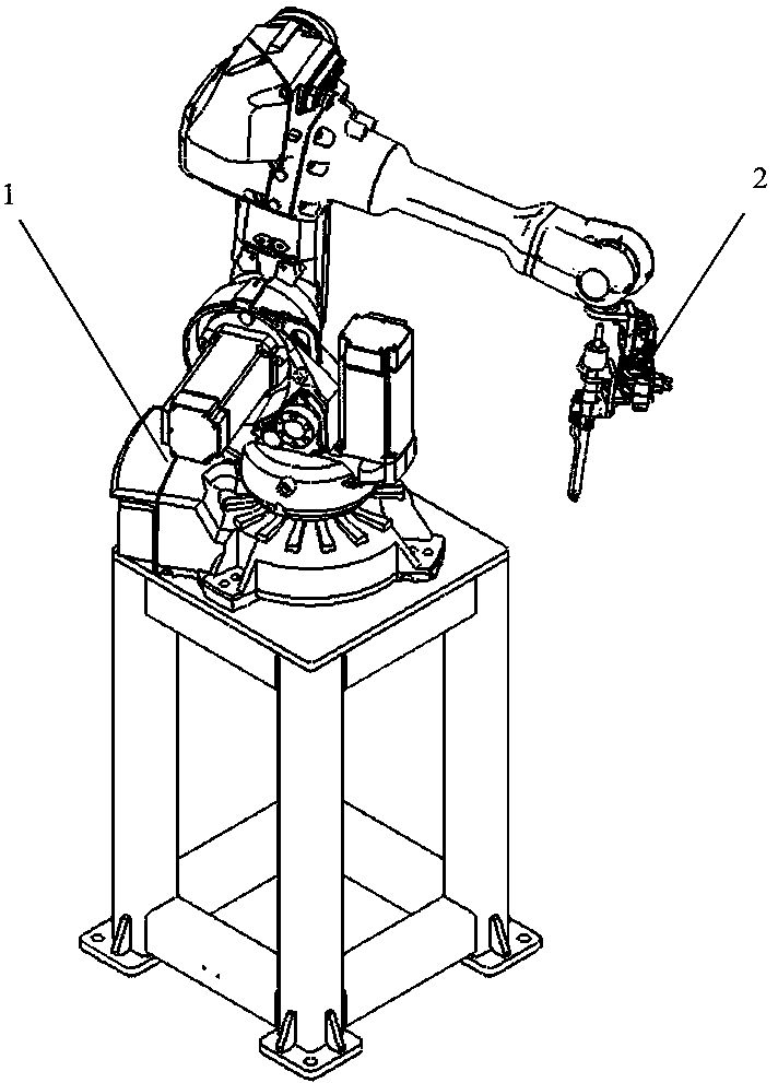
[0027] Such as Figure 1-2 As shown, the present invention provides an automatic ultrasonic flexible welding system, comprising: an ultrasonic welding mechanism, a welding station, a mold changing trolley 6 and a safety fence 7, and the ultrasonic welding mechanism includes: a welding robot 1, an ultrasonic welding device 2 and Welding gun storehouse 3, described welding robot 1 is fixedly installed by robot installation frame, and described welding robot 1 is connected with described ultrasonic welding device 2, and in order to speed up the welding process, two groups of welding robots 1 are set in the present embodiment, to the workpiece To carry out synchronous welding in partitions, the welding torch storehouse 3 is arranged in the middle of one side of the two groups of welding robots 1 for placing welding torches of different specifications, and the welding station is arranged between the two groups of welding robots 1 On the other side of the welding station, the weldin...
Embodiment 2
[0029] On the basis of the foregoing embodiments, further, as Figure 5 As shown, the ultrasonic welding device 2 includes: a welding head adjustment assembly and a quick-change welding head assembly, the welding head adjustment assembly and the quick-change welding head assembly are connected by a quick-change chuck, and the welding head adjustment The assembly includes: slide cylinder 20, chuck connecting plate 21 and chuck body R side 22, the three are connected sequentially from top to bottom, the quick-change welding head assembly includes: chuck body T side 23, welding torch mounting plate 24. Welding head installation frame 25, amplitude modulator and transducer 26, and welding head 27, the T side 23 of the chuck body is connected to the R side 22 of the chuck body, and the welding torch mounting plate 24 is installed on the chuck body Below the T side 23 of the disc body, the side end of the welding torch mounting plate 24 is connected to the welding head mounting fram...
Embodiment 3
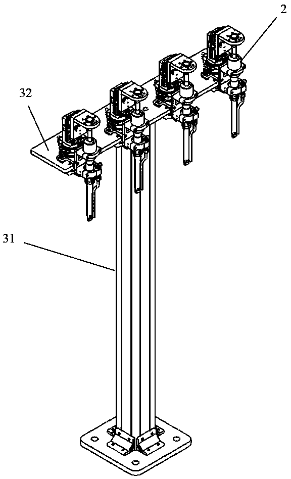
[0033] On the basis of the foregoing embodiments, further, as Figure 3-4 As shown, the welding torch storehouse 3 is composed of a base 31 and a welding torch fixing plate 32 installed above the base 31. Four groups of welding torch brackets 33 are arranged side by side on the welding torch fixing plate 32. The welding torch fixing plate Two positioning holes 241 are symmetrically arranged on the end of one side away from the welding head mounting frame 25 on the 24, and two positioning holes 241 are symmetrically arranged on both sides of each group of the welding torch holder block 33 to cooperate with the positioning holes 241. Locating pins 34, detection sensors 35 are also arranged between each group of locating pins 34 on the welding torch fixing plate 32, for detecting whether the quick-change welding head assembly is placed at this position, on the welding torch mounting plate 24 There is a space to cooperate with the detection sensor 35 .
PUM
 Abstract
Description
Claims
Application Information
 - Generate Ideas
- Intellectual Property
- Life Sciences
- Materials
- Tech Scout
- Unparalleled Data Quality
- Higher Quality Content
- 60% Fewer Hallucinations
Browse by: Latest US Patents, China's latest patents, Technical Efficacy Thesaurus, Application Domain, Technology Topic, Popular Technical Reports.
© 2025 PatSnap. All rights reserved.Legal|Privacy policy|Modern Slavery Act Transparency Statement|Sitemap|About US| Contact US: help@patsnap.com